®
www.climacoolcorp.com
10
Unit Placement
ClimaCool modular chillers must be installed in a conditioned
requirement for the chiller is a level surface capable of bearing
the combined operating weight of the modules
Service Access
The recommended service clearances are 36” for front
access, 18” height clearance for 30, 50 and 70 ton modules,
and 24” height clearance for 85 ton module, 30” for rear
access and at least 12” for side clearance or as required
on page 7). Local building or electrical codes may require
additional clearance – please consult applicable codes.
Draining
When performing standard maintenance procedures such
optional water isolation valves for this purpose. Access to a
procedures. Warning: Water valves must be reopened after
ushing is complete.
Assembling Modules
ClimaCool recommends locking down the chiller to a
the compressors are installed on anti-vibration mountings,
further isolation of the chiller from the structure is
recommended by installing vibration-eliminating springs
or pads under the base rails on which the chiller will rest
module should be chosen as the reference module and
carefully located.
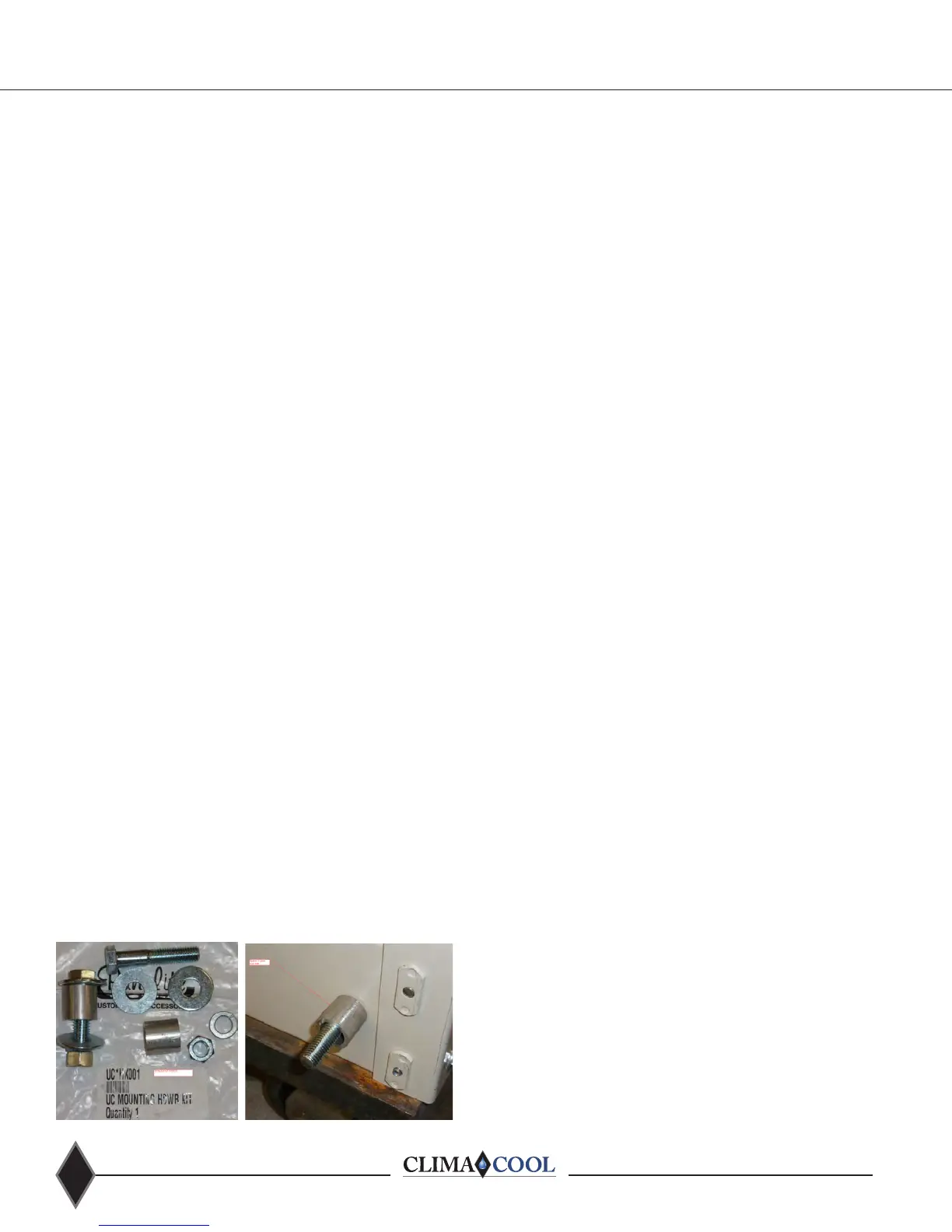
Field installed mounting accessories are provided for
adjoining each module.
•
grooved couplings with gaskets
• Mounting hardware kit containing necessary bolts,
spacers, nuts and washers
•
Field installing the mounting hardware kit will assist with
sides of the unit base pan. First module should be set, set
adjacent unit on mounting surface roughly aligned 1½ inches
and insert bolt through front mounting hole and spacer.
Repeat the process for the rear mounting hole. Line up
mounting hole of adjacent module with bolt from previous
module and working through adjacent modules front base
cutout place a washer, split lock washer and nut. Using the
appropriate tools tighten hardware assembly until seated.
Inspect the pipe ends to ensure they are free from any
indentations, projections, roll marks or other harmful surface
defects such as loose paint, scale, dirt, chips, grease and rust.
Inspect the grooved coupling gasket for any defects. Apply
a thin layer of silicone or other non-petroleum lubricant to
the sealing lips of the gasket as well as to the exterior of the
gasket. Install gaskets on the pipe ends of one of the two
modules to be mated. Be sure the gasket is completely on
the pipe to avoid damage in the next step. Move the second
module into position and line up the piping. Ensure you are
maintaining alignment for any additional modules to be
added. When pipe ends are aligned, slide the gasket over
the ends and center it between the grooves. No part of the
gasket should protrude into the groove of either pipe end.
Place the coupling halves over the gasket and make sure that
engaged into the grooves. Insert the bolts and install nuts to
hand tight. Ensure the oval neck of the bolt engages into the
bolt hole of the housing. Tighten nuts alternately and equally
until the bolt pads meet and make metal to metal contact.
Tighten nuts by another ¼ to ½ turn to make sure the nuts
and bolts are snug and secure; the use of a torque wrench
is usually not required. Uneven tightening of bolts may
cause the gasket to be pinched resulting in immediate
or delayed leaks.
Header Insulation
Chilled water piping is pre-insulated on each module at the
cell insulation. After bolting all modules together and leak
testing, the entire coupling connection will need to be
insulated by the installing contractor.
Unit Installation
Figure 6: Mounting Hardware Kit