11
®
www.climacoolcorp.com
Unit Installation
Figure 8: Gasket Installation Between Modules
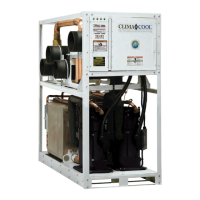
Figure 7: Header Insulation
Front Back
Grooved Couplings Installation
Inspect the pipe ends to ensure they are free from any
indentations, projections, roll marks, or other harmful
surface defects such as loose paint, scale, dirt, chips,
grease and rust. Inspect the grooved coupling gasket for
any defects. Grooved couplings are used to adjoin a bank
of modules. This requires the temporary removal of all
top, back and side sheet metal panels to obtain additional
couplings can be installed using the following recommended
instructions:
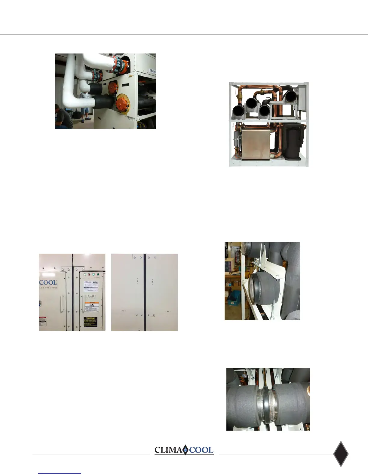
Figure 9 - UCW/H Side View
3
1
2
4
Figure 10
Figure 11
• Remove the rubber gasket from the coupling.
• Apply a thin layer of silicone or other non-petroleum
lubricant to both the inner and outer surface of the
gasket to reduce friction.
• Slide the gaskets on the headers as shown in Figure 10.
• Be sure the gasket is completely on the pipe to
eliminate any damage to the gasket.
• With gasket in place on each header of the positioned
position and line up the piping. Ensure alignment is
maintained for any additional modules to be added.
Sound Attenuation Panels and Gasket
Attenuation panels are enclosures made of 18 gauge
for installation between modules. Install panels by setting
in place and locking down with the half turn latches or
self tapping screws. Note: Panel package includes a
compressed 1” x 1” gasket sealant tape for installation
between modules
. Install the tape on the outer frame
on the side of one module prior to installing the adjacent
modules. See Figure 8.
• Review Figure 9, UCW/H Side View below.
• Headers are numbered indicating the easiest order of
coupling installation.
• UCW/H chillers should have couplings installed on
headers 1, 4 from the top and 2, 3 from the
back of the unit.