®
www.climacoolcorp.com
40
Engineering Guide Specications
General
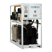
Factory-assembled and wired water cooled, water chiller.
Chiller consists of two compressors, one evaporator and
condenser, safety and operational controls. The modular
water cooled package chiller shall incorporate one or more
modules with two independent refrigerant circuits. Modules
shall be capable of independent operation powered by a
breaker) supplied by others, so that any one module can
be shut down for repair without interrupting the remaining
chiller modules in operation.
Basic Construction
The frame design shall consist of heavy gauge galvanized
resilience in transport and installation. The module must
have a low center of gravity, detachable schedule 40 carbon
steel pipe water headers, designed to connect to adjacent
modules through the use of 300 psi rated grooved cou-
plings, base with cutouts for forklift or pallet jack and the
doorway. Each module has sound attenuation panels to
ensure quiet operation.
Refrigeration Circuit
All refrigeration circuits shall contain R-410A non-ozone
depleting HFC. Each independent circuit shall consist of a
scroll compressor, thermostatic expansion valve for
low pressure safety controls. The modular chiller bank must
be able to produce chilled water even in the event of a
failure of one or more refrigerant circuits.
Evaporator
to-water, dual circuited, brazed plate heat exchangers
constructed of 300 stainless steel; designed, tested, and
UL stamped in accordance with ASME Section VIII pressure
vessel code for 650 psig working refrigerant pressure.
The evaporator heat exchanger shall be mounted to
evaporation with consequent liquid slugging on startup.
The evaporator shall be mounted on two layers of noise
attenuating rubber isolation pads which also act as a
closed cell insulated blanket. The closed cell insulation s
hall be provided on suction side refrigerant tubing
including refrigerant-to-chiller heat exchanger to
prevent condensation
Condenser
to-water, dual circuited, brazed plate heat exchangers
constructed of 300 stainless steel; designed, tested, and
UL stamped in accordance with ASME Section VIII pressure
vessel code for 650 psig working refrigerant pressure on
the condenser. The condenser heat exchanger shall be
the cold evaporation with consequent liquid slugging on
startup. The condenser shall be mounted on two layers of
noise attenuating rubber isolation pads which also acts as a
thermal barrier.
Compressors
Each module shall contain two scroll compressors
independently circuited for redundancy. Each compressor
shall be mounted with rubber isolated compressor mounts
to the module base and each shall include compressor
overload protection, high discharge pressure and low
suction pressure cutouts.
Control Panel
Master Controllers shall be provided for individual control
as well as system integration. The control shall consist of
a simple two-conductor shielded daisy chain connection to
wiring. The remote air cooled chiller control panel shall
be a NEMA Type 1 enclosure including: power distribution
fusing, transformer, isolation relays, status and alarm
relay, 16-bit microprocessor master controller with built in
2) unit alarm status, 3) power on, two toggle switches to
disable each individual compressor during start-up
or troubleshooting.
CoolLogic Control System
Remote Master Control system shall be fully compatible
with the Building Automation System via native BACnet and
LonWorks, Modbus and N2 communication. Scheduling
of the various compressors shall be performed by the
master microprocessor based controller. A compressor
run time equalization sequence is provided to ensure even
distribution of compressor run time. A load limit control
shall be available to limit the number of compressors that
can be energized at one time.
The CoolLogic Control System shall monitor and report the
following for each refrigeration circuit in each module:
• Discharge pressure and temperature faults
• Suction pressure and temperature faults
• Compressor winding high temperature fault
• Low evaporator leaving chilled water temperature fault