®
www.climacoolcorp.com
46
Operation Instructions
Flush valve line must be piped to atmospheric pressure such
changes in elevation and should be sloped downward in the
direction of drainage. Do not pipe the ush or drain line into
a pressurized line.
Note: The Automatic Timer Flush Package needs to be
programmed when it is received by the end-user. The
programming is simple and takes only a few moments.
However, because every application has dierent
parameters that aect the required frequency between
ushes and the duration of the ush, the end-user must
choose the controller’s settings (refer to your specic
strainer manual).
To Program the ATF Controller
1. Plug the transformer into a 120-VAC outlet.
2. Insert the 12-VDC plug coming from the transformer into
the jack on the underside of the ATF box.
3.
the valve will start to open).
4.
inner timer ring with the GREEN POINTER clockwise to
increase duration. The ON TIME RANGE is factory set at
5.
outer ring with the RED POINTER clockwise to increase
duration. The OFF TIME RANGE is factory set at twenty-
6.
on the timer will come on and the upper light on the
the on light on the timer and the lower switch light will
come on.
Control Switch
down the manual control switch located on the front of the
can also be used to conveniently drain the water out of the
strainer before removing the conical screen element from the
strainer housing. A yellow indicator arrow on top of the ATF
valve will rotate in sync with the ball valve to show the valve
switch is released, the valve will automatically close.
SAFETY FIRST! - Keep ngers away from valve opening to
avoid getting caught in the moving parts. The electric motor
supplied a sucient amount of power to cause personal
injury. Take precaution when handling.
Water Resistance
The valve and controller are water-resistant, but not
water-proof. Do not install below ground level where the
component can be submerged in water. Only remove
the cover plate from the valve controller when setting or
the unit during normal operation.
Pressure Dierential Alarm Package Option
monitors and displays the strainer’s inlet and outlet
alert maintenance personnel that the strainer element
on page 43).
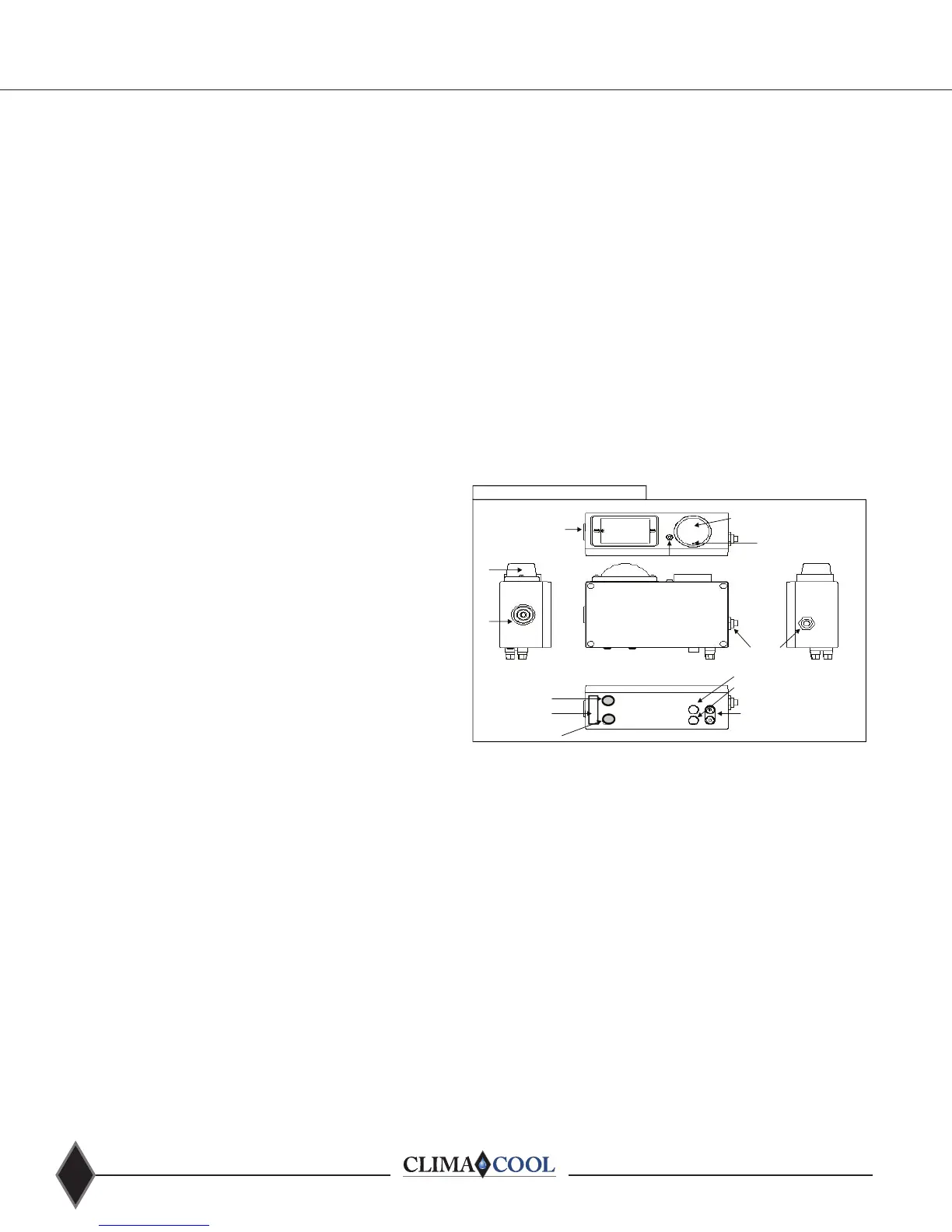
Figure 32
PSID High
PSID Low
PRESSURE DIFFERENTIAL ALARM PACKAGE
Alarm Reset Button
FRONT
VIEW
LEFT SIDE
VIEW
Power To ATF
110 Volt/12 Volt DC
Wall Transformer
Visual
Alarm
Audible
Alarm
Pressure Dierential
Switch-Gauge
LED Power Indicator
Dierential
Set-Point Contact
Cover-Plate Screw (4) in Corners of
Box (DO NOT REMOVE).
Visual
Alarm
RIGHT SIDE
VIEW
TOP
VIEW
BOTTOM
VIEW
AUX Contacts
(On or O with Alarm)
Red & Black
Cable Retainer
Operation Instructions
Remove the power supply and insert the connector end into
32 above) and plug the transformer into the power source.
Standard systems are supplied with a 120V power supply to
the primary of the transformer, with an output secondary of
clogged and require immediate removal and cleaning. To
Note: It is not
recommended to set the dierential switch-gauge higher
than 10 psi. Disabling the alarm or increasing the alarm set
point could result in damage to the strainer element and
allow debris to pass into the system.
Stainless Steel Strainer Option