INSTALLATION
6
SeeleyInternationalPtyLtd
Cooler location
Check the proposed cooler location, to ensure that it is structurally capable of supporting the weight of the cooler, or provide an
adequate alternate load bearing structure.
Always locate the cooler where it will receive a plentiful supply of fresh air; NOT in a recess where it may be starved for air or
where the air is polluted.
Air exiting the exhaust hood is warm and heavily laden with moisture. Ensure the cooler’s exhaust outlet location will not cause
corrosion or damage to other nearby items.
Allow adequate access to and around the cooler for maintenance. Provision must be made for access to electricity, water
supplies and drains. Note: Do you need to discuss the installation of items like safety anchor points with the customer?
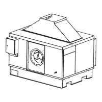
• Ensure the location is a minimum of:
3.0m from a solid fuel heater flue,
1.5m from a gas flue,
5.0m from a sewer vent
Rear = Min from a wall, at sides
to allow easy access for maintenance and core replacement.
!
!
!
!
Do not allow exhaust air to re-circulate into the air intake of the cooler.
1.0m 1.6m
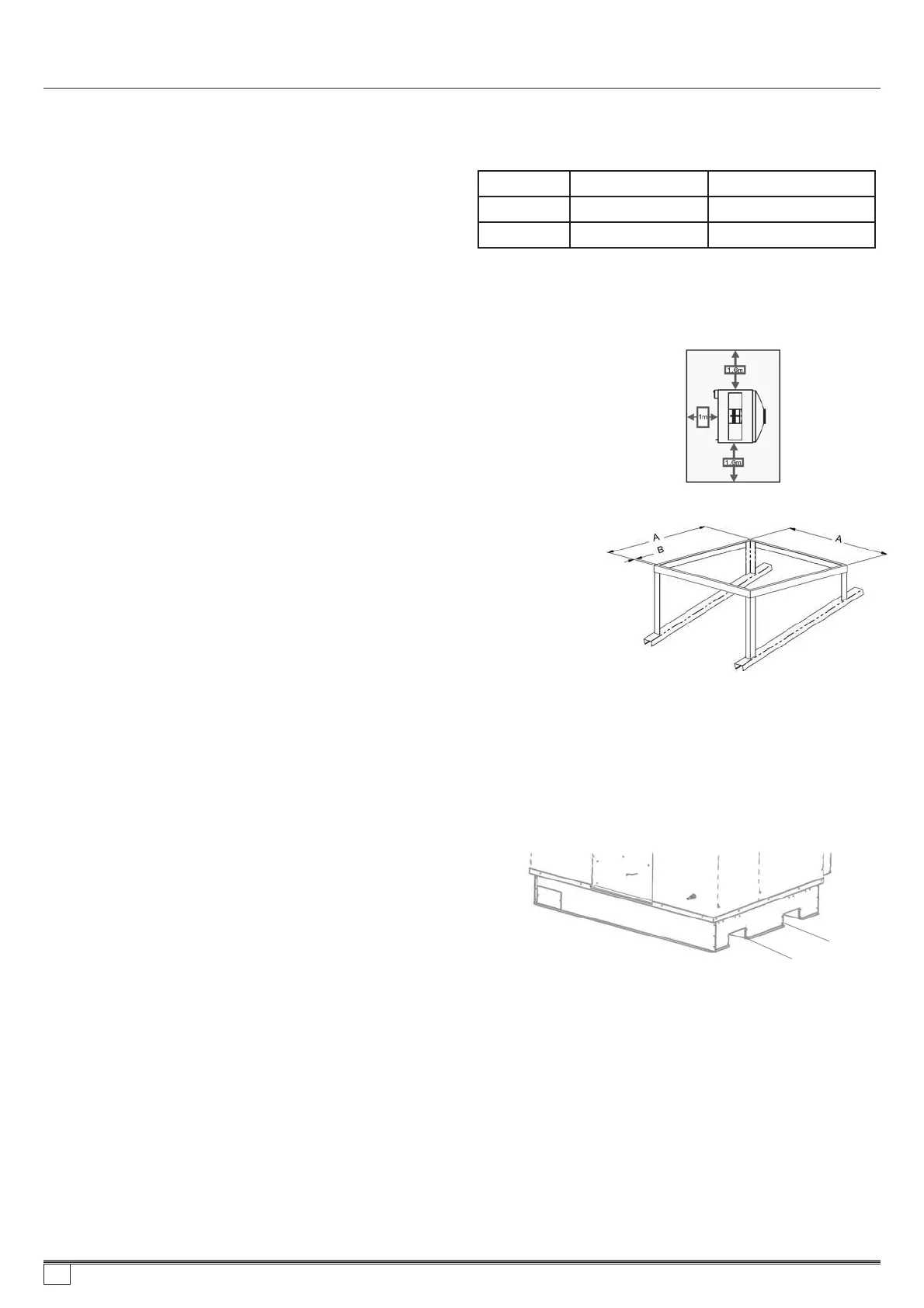
Mounting/support
Unpackingthecooler
Movingthecooler
Liftingthecooler
Vibrationisolation
Industrystandardsupportframescanbeusedwiththiscooler.
Recommendedsteelspecification:
50*50*3mmRHSGalvanisedorPainted
Thecoolerwillbedeliveredwrappedinaplasticstretchwrapfilmwhichwillneedtoberemovedbeforeinstallation. A
smallbagofInstallationcomponentsalongwiththeexhausthoodsheetmetalcomponentscanbefoundunderthelidof
themaincabinetofthecooler. Thelidwillneedtoberemovedandtheexhausttransitioncomponentsassembledand
fittedtothelidbeforere-installingthelidassemblybackontothecooler. Thewallcontrolandcommunicationscable,
alongwithancillarymountplates,fastenersanddrainadaptorswillneedtobeplacedasideforlaterconnection.
Thecoolerhasin-builtfork-trucktyneopeningsinthebaseforeaseofmovement. Theopeningscanalsobeusedwith
liftingstrapsorslings(referdiagram&seebelow)
Thecoolermaybeliftedeitherbyfork-truckorcranewithslings. Themethodforliftingbycraneisbyliftingstrapsthrough
thecoolerbasefork-trucktyneopenings.Donotattempttoliftusinganycabinetfeaturesorbyretro-fittingliftinglugs. The
cabinetmaybedamagedand/orliftsafetycompromised.
Itisrecommendedtouseaspreaderbaronthestrapsorslingsand/ortoprotecttheupperedgesofthecoolerwitha
cornerprotectorbeneaththeliftingstrapstoavoidanydamagetothecabinetduringthelift.
Wafflepadsarerecommendedtobeusedundereachcornerofthecooler.Padsizeapprox.200*200mm.Useindustry
standardmethodsoffixingtothebuildingstructure.
Min.Forktynegap
=460mm
CW-H10 A =1300*1206
1300*1800
CW-H10&15B=50min
Angletomatchroofpitch
CW-H15 A =
Model
CW-H10 180kg 220kg
265kg225kgCW-H15
ShippingWeight OperatingWeight
859736-A AU1007