B-43
Options
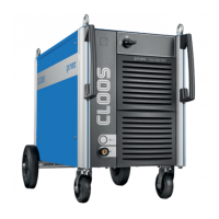
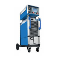
GLC 353/503/553 MC3
O4 Automation interface
An automation interface is used if a coupling between the power source and external controls
(i.e. PLC control) is required. The following external signals can be received via automation
interface:
- Selection of a welding process
- analogue inputs for control of wire feed speed/capacity and voltage/arc length
- digital input for continuation of capacity 1, 2, 3 in operation mode Prog
- digital input for external Start and external Gas
The signals
- arc present
- collective fault
will be sent to external controls.
Accessories coding according to the following list is required!
Resistance values for coding of accessories (remote controller etc) to GLC 353/503/553 MC3.
For coding accessories to the power source a resistor must be instelled between +10V and the
inputs X7/C4 (remote controller socket on wire drive unit) or X15/B7 (peripheral socket).
In the case of the MC3/R a bridge is required beween X15/28 and X15/31.
It is recommended that the resistor is installed in the plug of the remote controller or the
connection cable of a higher voltage control so that the coding is only applicable if the relevant
unit is connected to the power source.
CAUTION ! If a remote controller and a higher voltage control (e.g. a robot) are simultaneously
connected, coding is only allowed on one of the two plugs.
Coding is carried out in steps of 1 Volt, the resistor to be installed represents the upper arm of
a voltage divider. The lower voltage divider is already provided in the control.
The following resistance values are used to set the corresponding voltage level:
8,2 k Ohm 1V Remote controller 038 05 01 00 connected to CK
3,6 k Ohm 2V
2,2 k Ohm 3V
1,3 k Ohm 4V
910 Ohm 5V 1.) Change-over to external set values (control voltage 5+6
above X15)
2.) ST 104 MC3:
The 2nd torch trigger is only used for change-over to CK 2;
welding on with external start.
620 Ohm 6V ST 104 MC3:
The 2nd torch trigger is only used for change-over to CK2;
welding on with external start.
390 Ohm *7V 1.) Change-over to external set values (control voltage 5+6
above X15)
2.) Wire currentless with torch trigger
220 Ohm 8V
100 Ohm *9V Wire currentless with torch trigger
0 Ohm 10V Robot version
* Version 1.50 and higher
O4 Automation interface