CNC-STEP GmbH & Co. KG ▪ Siemensstrasse 13-15 ▪ 47608 Geldern ▪ Germany
Support: +49 (0)2831/91021-50
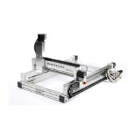
4.3.4 X-ax i s w i th carria g e
The Fig. shows the X-linear guide (Fig. 10a / 2) with trapezoidal
threaded spindle (Fig. 10a / 3) from one side of the machine.
The second X-linear guide with trapezoid thread spindle is
positioned symmetrically on the other side of the machine.
The two linear guides represent the X-axis, on which the Y-
bridge is moved (Fig. 10a / 1) along the X linear guides.
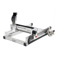
The reference switch (Fig. 10b / 1) responds to the magnetic
field of the incoming homing magnet (Fig. 10b / 2). If the
magnet is close enough the reed sensor of the switch turns on.
The reference switch operates as closing contact; in switched
state the signal circuit is closed.
HINT:
Reference switches are required for axes without absolute position encoder to
feature in the initialization of the axis by a known reference point (zero point of the
axis). From this position, all other positions are then calculated relative to the
process of the axis via software.
 Loading...