CNC-STEP GmbH & Co. KG ▪ Siemensstrasse 13-15 ▪ 47608 Geldern ▪ Germany
Support: +49 (0)2831/91021-50
6.3.2 Conn e ct i ng t h e ste pp er moto r an d co nt rol ca bl e
ATTENTION:
Risk of tripping and falling!
Exposed wires on the ground can lead to tripping or slipping.
• On the ground laid cables should be covered.
• Do not lead past corners and sharp edges.
• Avoid chafing.
• Visibly mark line course.
The connectors of the stepping motor, and control lines (Fig. 23
/ arrow) are labelled.
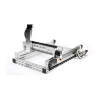
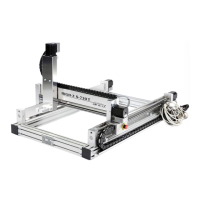
Fig. 24: Stepper motors of axes
Connect the plug of the stepper motor and control cable
with the following assignment to the stepper motor
controller:
• X-axis stepper motor (Fig. 24/1) to terminals X1 and
X2 of the stepper motor controller
• Y-axis stepper motor (Fig. 24/2) to terminal Y, the
stepping motor control
• Stepper motor Z-axis (Fig. 24/3) to terminal Z of the
stepper motor control
• Emergency stop switch, limit and reference switches
to port ST stepper motor control
Secure cable connections with the knurled screw from
loosening.
 Loading...