CNC-STEP GmbH & Co. KG ▪ Siemensstrasse 13-15 ▪ 47608 Geldern ▪ Germany
Support: +49 (0)2831/91021-50
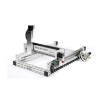
Fig. 34: Cover Y-axisBall nut X-axis
(2 pcs)
Turn the machine off and secure it against being
switched on again.
Loosen and remove the four screws (Fig. 34/2)
Cover (Fig. 34/1) to remove the Y-axis.
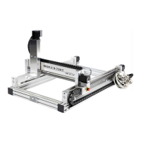
Fig. 35: X-axis ball screw
Clean the both ball screws on the x-axis.
With a paintbrush or a clean lab put grease on the
spindles.
Drive the machine a few times on the x-axis.
Fig. 36: ball screw Y-axis
Please use the same procedure like No. 4-6
Attention: Risk of health damage by contact with oil and grease!
Contact with oil and fat can lead to health damage.
• Avoid skin contact.
• Remove oil and grease from the skin immediately
• Do not inhale vapors.
 Loading...