Inputs
By default, all MB3 inputs are 24V tolerance for industrial sensors and switches.
However, sometimes we need to interface with 5V devices, such as MPG and low
voltage sensors. On page 25, topic [*6]. 5V input tolerance shows the way to makes
the MB3 board accepts low voltage. It is recommended to use shielded cable with
shield grounded to one side only star configuration. Placing terminals or ground lugs
close to the MB3 makes for neater wiring to land shields and 0 or 5/24Vdc. The neater
your wiring the easier to work with or add to. You should also consider the whole
wiring scheme before wiring as you do not want to continually cross wires as this
makes for a rats nest.
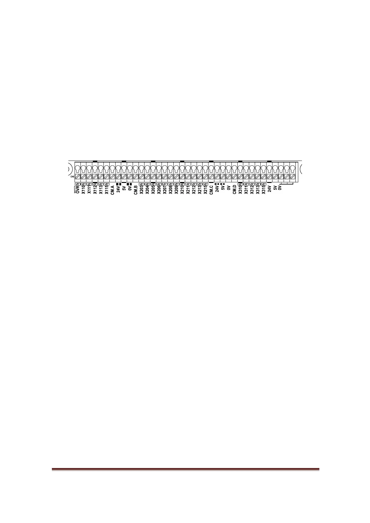
Figure 9, Input terminals
Figure 9 shows 23 input terminals. There are all universal inputs, divided into 4 main
groups. Each group has its own common terminal.
CM.A (OVR, X110, X111, X112, X113, X115)
CM.B (X203, X204, X205, X206, X207, X208)
CM.C (X209, X210, X211, X212, X213, X215)
CM.D (X310, X311, X312, X313, X315)
The common pin is used to select NPN or PNP. For example if CM.A connects to 24V, all
inputs in this group become NPN type and it waits for 0V to be presented at the X1xx
terminal to make input active, the status LED will lights up.
On the other hand, if CM.A connects to 0V, all inputs in this group become PNP and it
waits for 24V to be present at X1xx the terminal to make input active, the status LED
will light up.
By default all inputs accept 24V, However if 5V input is preferred for particular inputs
the user can bridge the solder-bridge underneath of MB3 board.
www.CNCRoom.com Page 14