Small Adjustment
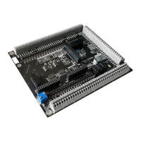
Figure 23, Analog output adjustment POT
Even though the MB3 board has been fully tested and calibrated before shipping. The
suitable analog output may be slightly different from the actual with any VFD. There is
a multi-turn POT (Potentiometer) that allows us to gradually shift the whole range of
actual-line up or down over command-line by mV unit as appears in Figure 23. Turning
clockwise will shift voltage up and counter clockwise will shift the voltage down. We
could use a nail tip as a tool to turn adjustment screw for small adjustment.
Full Adjustment
1. Setup and connect volt meter leads to AG (Analog Ground) and AO (Analog
output) terminal.
2. In ESS configuration, set spindle maximum speed to 10000 RPM and the
PMW frequency at 260hz.
3. In Mach3/4 software, entry command S10000 M3 in MDI and execute it. This
commands Mach3/4 to generate 100% duty cycle for PWM.
4. Turn adjustment screw of the POT counter clockwise to decrease voltage or
do it in the opposite way to increase voltage until voltage meter read value
about 10.04 Vdc.
5. In Mach3/4 software, entry and execute other PWM duty cycle by
commanding spindle speed such as s5000 for 5V, s1000 for 1V, s500 for 0.5V
then read actual value from volt meter and do small adjustment until you
found best result for your work.
6. After finishing adjustment, now you can change maximum spindle speed in
Mach4 configuration back to actual maximum speed. Please see Figure 77
on page 50.
Note.
1) There is ±1.2% error in some area and 0% error in some area. The user
must decide which outcome is the best for his work.
2) Be careful of using metal screw driver, it can slip off from your hand and
accidentally make a short circuit to the circuit board.
www.CNCRoom.com Page 21
 Loading...