Appendix III Safety circuit options
The circuits shown below are only examples and adhere to no particular country’s safety
standard. Please always seek professional advice from a qualified electrician or electrical
engineer in your country of residence before implementing any circuit that is presented in this
manual. CNCRoom cannot be held responsible for any adverse outcome, which came about as
a result of copying anything from this manual.
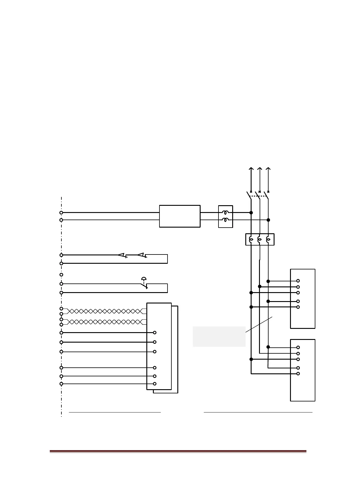
Safety Circuit 1
Safety circuit 1 is simple but effective. It has fewer components and less wiring and relies
mainly on good and consistent function of the computer and electronic components to
disengage the drive’s power through a “servo on” signal or similar.
PANASONIC MINAS-A
Step command
Series of limits switches
0V
X115 (Limit signal)
PANASONIC MINAS-APANASONIC MINAS-A
MB3 Board
Servo Drive
Power circuit
Noise Filter
0V
24V
24V
0V
E-Stop
0V
X203 (E-Stop signal)
Servo On
Y316
0V
24V
24V
Fault (Drive2)
0V
X209 (Fault input)
X210 (Fault input)
Fault (Drive1)
Direction command
External Circuit
Control power and
Main power
Servo Drive
Control circuit
24Vdc
Power supply
To main power
1ph or 3ph
Circuit
Breaker
Noise Filter
Figure 81, Safety Circuit 1
1. Make X203, X209, and X210 as inputs of safety circuit
by soldering their bridges underneath of MB3 board. Then
assign X202 as the E-Stop input.
2. Assign X115 as Limit input
3.Assign Y316 as Enable2.
www.CNCRoom.com Page 54