VCC
70 mA (max)
L
L
*
0V
24V
Yxxx
Figure 19, connecting various loads to a “Y” output
Relays
The MB3 comes with three relays; those are K1, K2 and K3. All relays provide NO or NC
contacts. The K1, K2 also provides an “OFF Delay” feature. To activate this feature the
user needs to follow the instructions as set out on page 24 , topic [*4]. Off Delay timer.
These three relays are signal relays and should never be used as power relays. They
are intended to convey signals such as forward and reverse to a VFD (Variable
Frequency Drive) to control motor rotation of a spindle or similar. They can be used for
other purposes as well, and the user needs to map them in Mach accordingly.
However, please take care, as the contacts of these relays can carry a maximum
current of only 0.5 Amps at 120VAC, or 1 Amp at 24Vdc. The user must use an external
relay if the load requirements of the device will exceed the aforementioned current
rating.
Charge Pump
Charge pump is pulse frequency signal from Mach3/Mach4 indicating that Mach is
present and ready to run. MB3 has special circuit to capture this pulse frequency and
output to CP (Charge Pump) terminal. Normally an external relay would be connected
to this CP terminal for cutting the power source from any attached loads. However, the
user can choose to select K3 as an output for the CP signal. To choose this option,
Please see [*7]. K3 Relay pin select on page25.
NO3
CM3
SPD
24V
Yxxx
MB3
External circuit
Solder bridge
*7
CP selected
24V
CP
24V
SPD
Yxxx
MB3
External circuit
Figure 20, Charge pump interlock with other relays
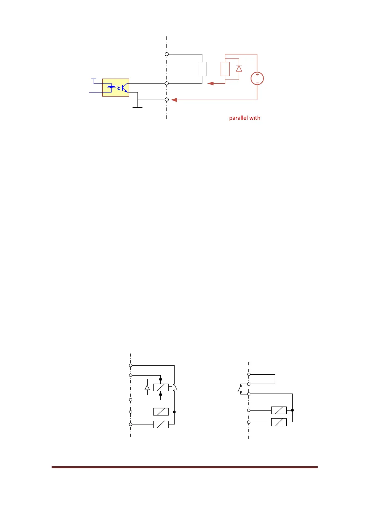
5-30Vdc
* A diode is needed in
parallel with the coil
MB3 External circuit
www.CNCRoom.com Page 19