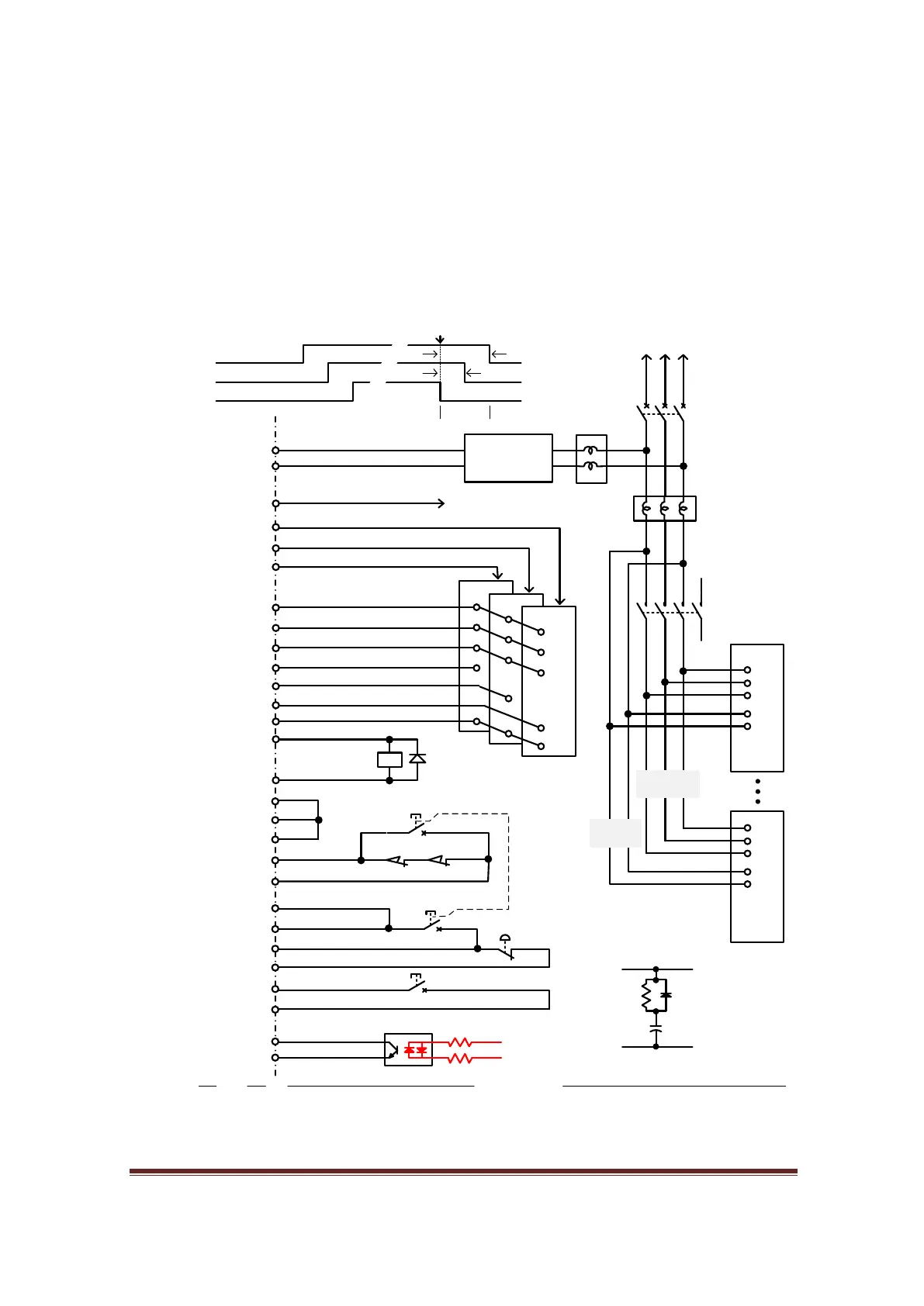
Safety Circuit 3
Since the MB3 board supports an “Off-Delay” function for relay K1 and K2, it allows the user to
create a timing sequence for devices that need to power up or power down independently at
different times.
In this circuit an AC line monitor for recognising a “Power-Out” or “Black-Out” condition has
also been introduced. This circuit will halt the machine in an orderly fashion before it loses
power completely. A UPS is needed to power AC drives for few seconds after the power has
failed. For DC drives a lower cost, slow charging capacitor is all that is necessary.
M1
24V
Y Step, Dir command
NO2 (Y214)
M1
Drive NDrive 1
Servo Drive
Power Cicuit
Noise Filter
Circuit
Breaker
Magnetic
Contactor
To main power
1ph or 3ph
1N2004
Control
power
Main
power
0V
24V
Noise Filter
Servo On
Alarm clear
Y316
NO1 (Y201)
24V
24V
Fault (Drive2)
0V
X208 (Fault input)
X209 (Fault input)
Fault (Drive1)
External Circuit
(Bridge time delay)Enable2
(Bridge time delay)Enable4
24Vdc
Power supply
mechanical brake
Y314
Enable6
Series of limit switches
0V
X115
Release.1
Limit
OVR (Override)
X110 (Reset)
E-Stop.1
0V
X203 (E-Stop)
Release.2
(OEM code 1021)Reset
(Bridge safety circuit)E-Stop
X204
(OEM code 1000)CycleStart
22K 1W x2
AC Line
Monitor
X207 Power Failure
0V
PC814
CycleStart
X Step, Dir command
PANASONIC MINAS-A
Z Step, Dir command
Fault (Drive3)
X210 (Fault input)
Drive Control Cicuit
For drives do not
support brake
MB2
MB3
0V
CM2
0V
CM1
(Bridge safety circuit)
Enable2, NO2
Enable6, Y314
Enable4, NO1
Off delay
660ms
440ms
Mag Contactor
Brake
Servo On
Output Timing
E-Stop Event
DC bus
capacitor
Slow charging
0v
V+
(Bridge safety circuit)
(Bridge safety circuit)
(Bridge safety circuit)
Figure 83, Safety Circuit 3
www.CNCRoom.com Page 56