Quick Reference
Power Supply
24
Vdc
Drive
*Output can sink current up to
70 mA
L
L
L
L
L
L
L
L
L
L
L
L
L
Shrinkage part
24V
0V
Common 0V for PNP inputsCommon 24V for NPN inputs
NO, NC contacts x3
VFD
Inverter
A-IN
0V
<< Two types of wiring are
given as an example.
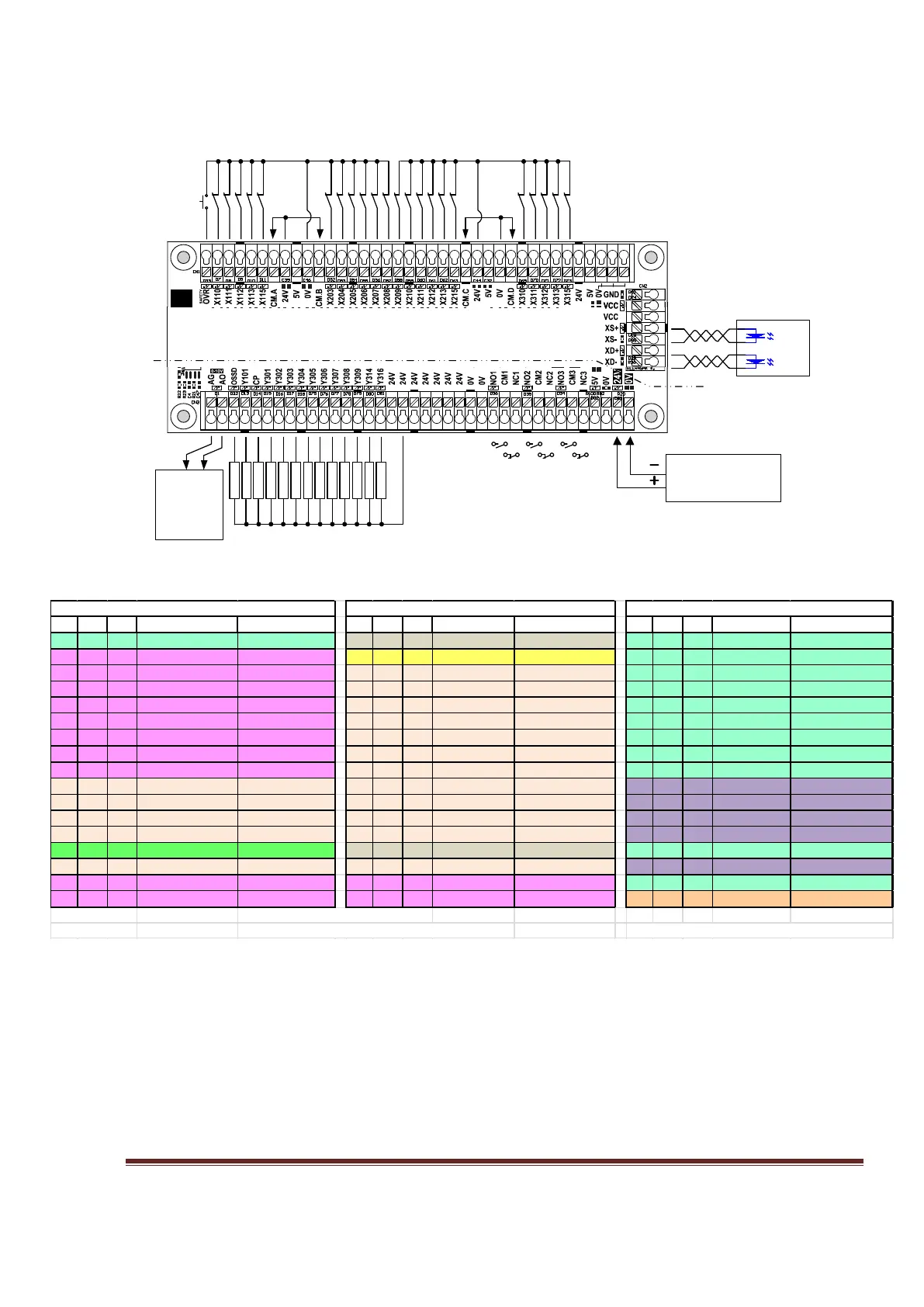
Figure 1, MB3 Overview Connection
Table 1, Ports and Pins Reference Tables
Quick Reference is a summary for the experienced users.
Figure 1 is a shrinkage view of MB3 board. It shows the connection of inputs & outputs, power supply,
analog output for the VFD and axis signals.
Table 1 is a summary of Ports and Pins and their corresponding reference numbers. All pin numbers
preceded by an “X” are inputs and if preceded by a “Y” are outputs. Using X110 as an example. The
“X” means it is an input. The first digit “1” is the port number, the last 2 digits “10” is the pin number.
Pin I/O Act Term Name I/O Type Pin I/O Act Term Name I/O Type Pin I/O Act Term Name I/O Type
1 O H SPD(Spindle) Sink output 1 O H NO1 Relay1 Contact 1 O H Y301 Sink output
2 O L XS (X Step) Line driver 2 I L OSSD
SafetyFeedBack 2 O H Y302 Sink output
3 O L XD (X Dir) Line driver 3 I L X203 NPN/PNP input 3 O H Y303 Sink output
4 O L YS (Y Step) Line driver 4 I L X204 NPN/PNP input 4 O H Y304 Sink output
5 O L YD (Y Dir) Line driver 5 I L X205 NPN/PNP input 5 O H Y305 Sink output
6 O L ZS (Z Step) Line driver 6 I L X206 NPN/PNP input 6 O H Y306 Sink output
7 O L ZD (Z Dir) Line driver 7 I L X207 NPN/PNP input 7 O H Y307 Sink output
8 O L AS (A Step) Line driver 8 I L X208 NPN/PNP input 8 O H Y308 Sink output
9 O L AD (A Dir) Line driver 9 I L X209 NPN/PNP input 9 O H Y309 Sink output
10 I L X110 NPN/PNP input 10 I L X210 NPN/PNP input 10 I L X310 NPN/PNP input
11 I L X111 NPN/PNP input 11 I L X211 NPN/PNP input 11 I L X311 NPN/PNP input
12 I L X112 NPN/PNP input 12 I L X212 NPN/PNP input 12 I L X312 NPN/PNP input
13 I L X113 NPN/PNP input 13 I L X213 NPN/PNP input 13 I L X313 NPN/PNP input
14 O H
Sink output 14 O H NO2 Relay2 Contact 14 O H Y314 Sink output
15 I L X115 NPN/PNP input 15 I L X215 NPN/PNP input 15 I L X315 NPN/PNP input
16 O L BS (B Step) Line driver 16 O L
Line driver 16 O H Y316 Sink output
17 O L BD (B Dir) Line driver 17 O L CD (C Dir) Line driver 17 O H AO Analog output
L=Low Active Analog PWM frequency = 260hz
H=High Active NO3 Relay3 can be controlled by Y101, Y317, CP LPT3 all inputs are high speed inputs.
Port2 (Pins 2-9 as input)
Port3 (Pins 2-9 as output)
www.CNCRoom.com Page 6