Safety Circuit 2
Safety circuit 2 is more for the user who prefers not to rely on electronics for safety and would
prefer the option of disengaging power from the drives or hazardous devices by the use of
unintelligent components, such as limit switches, the Estop button or a magnetic contactor.
In a situation where a motor runs out of control, being caused either by electromagnetic
interference or even human error, a well-designed system should be able to halt the machine
by the use of limit switches alone or by hitting the Estop button.
However, in normal circumstance, the MB3 with an external circuit and connection to a
computer should work well together. In some drive connections you may need to implement
the use of timer relays to handle an “Under Voltage” error.
PANASONIC MINAS-
A
M1
24V
NO2 (Y214)
E-Stop.2
Step command
Series of limit switches
0V
X115 (Limit signal)
M1
PANASONIC MINAS-A
PANASONIC MINAS-A
MB3 Board
Servo Drive
Power Cicuit
Noise Filter
Circuit
Breaker
Magnetic
Contactor
1 body, 2 contacts
On board relay
1N2004
Control
power
Main power
0V
24V
24V
0V
OVR (safety override)
X110 (Reset signal)
E-Stop.1
0V
X203 (E-Stop signal)
Reset
M1
Servo On
Alarm clear
Y316
0V
24V
24V
Fault (Drive2)
0V
X209 (Fault input)
X210 (Fault input)
Fault (Drive1)
Direction command
External Circuit
Limit override
Servo Drive
Control circuit
Noise Filter
24Vdc
Power supply
To main power
1ph or 3ph
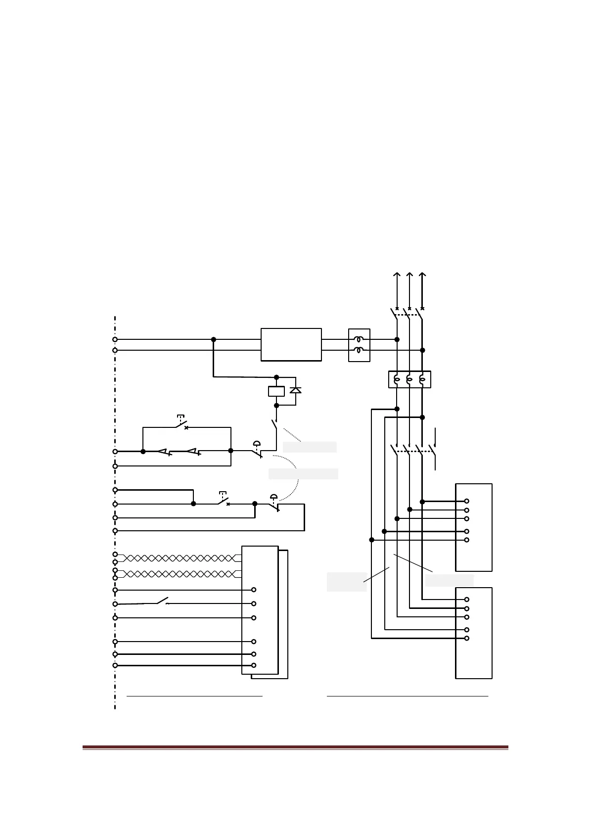
Figure 82, Safety Circuit 2
1. Make X203, X209, and X210 as inputs of safety circuit
by soldering their bridges underneath of MB3 board.
Then assign X202 as the E-Stop input.
2.Assign X115 as Limit input
3.Assign X110 as OEM Trigger, Then assign “Reset OEM
code” or 1021 to System hotkey > External button.
4. Assign Y214, Y316 as Enable1, Enable2 respectively.
www.CNCRoom.com Page 55