Analog
VFD
MB3
AO
AG
CM1
NO1
K1
PMW
AnaSpeed2
0V
5V
Forward signal
0-10V
GND
Analog input
External device
CM2
NO2
K2
Reverse signal
Alarm
0V
24V
X210
CM.C
0V
24V
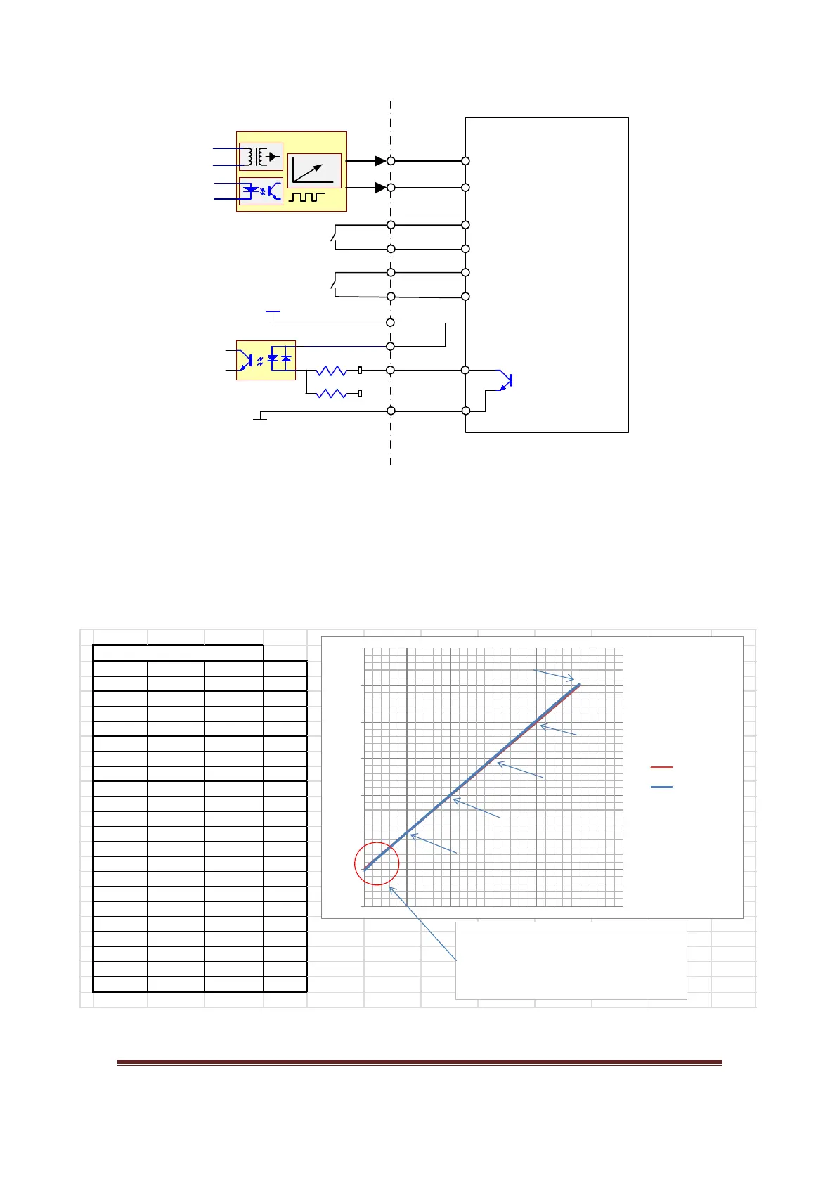
Figure 21, VFD connection
The “AnaSpeed2” circuit converts PWM signal to analog signal 0-10V. Using this analog
output with any VFD, the user must program VFD parameters to accept 0-10V.
Normally, a VFD needs a forward command to rotate the motor. Thus, any NO contact
of K1, K2 or K3 can be used for this purpose.
Figure 22, 0-10V Analog output characteristic
PWM Freq =260hz
Cmd Actual PWM Err %
0.00 -0.093 0% -9.30
0.50 0.480 5% -4.00
1.00 0.988 10% -1.20
1.50 1.495 15% -0.33
2.00 2.002 20% 0.10
2.50 2.509 25% 0.36
3.00 3.016 30% 0.53
3.50 3.523 35% 0.66
4.00 4.030 40% 0.75
4.50 4.537 45% 0.82
5.00 5.044 50% 0.88
5.50 5.551 55% 0.93
6.00 6.056 60% 0.93
6.50 6.564 65% 0.98
7.00 7.071 70% 1.01
7.50 7.577 75% 1.03
8.00 8.084 80% 1.05
8.50 8.591 85% 1.07
9.00 9.096 90% 1.07
9.50 9.602 95% 1.07
10.00 10.050 100% 0.50
-2.00
0.00
2.00
4.00
6.00
8.00
10.00
12.00
0% 20% 40% 60% 80% 100% 120%
Command
Actual
PWM Freq 260hz
Error
±
1.2% between 1-10V
Note
An a Speed2 start givi ng power from 0.05V to
10Vdc. But, mos t BOBs in the ma rket won't.
At off state or 0% it gives a weak negative voltage
to e ns ure s pindle is tu rned o ff.
This graph is tested on Mach4.
www.CNCRoom.com Page 20