Smart Ethernet Switch Series User’s Manual
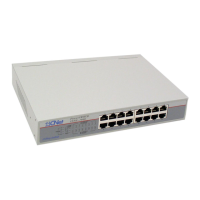
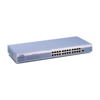
Table 2-2 The Front Panel: Switch
MODEL LABEL DESCRIPTION
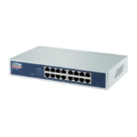
16 ports TX
with 1 FX
smart
switch
SW Select the activation of Ethernet port 8 or fiber port.
Low position: fiber port is selected.
High position: Ethernet port 8 is selected.
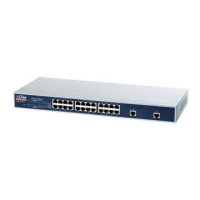
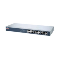
24 ports TX
with 2 FX
smart
switch
SW1/
SW2
There are two selection switches on the front panel. Select the
activation of Ethernet port 12/24 or fiber port 1/2.
Low position: fiber port 1/2 is selected.
High position: Ethernet port 12/24 is selected.
2.4.1. Ethernet Port Connections
For 10/100 Mbps Ethernet connections simply connect a computer or network device to a
port on the smart switch using an Ethernet cable.
The 16 ports TX with 1 FX smart switch and the 24 ports TX with 2 FX smart switch
come with one and two fiber uplink ports respectively for connecting to a high-speed server or
inter-connecting with another switch. On the 16 ports TX with 1 FX smart switch, the uplink
port is shared with Ethernet port 8. On the 24 ports TX with 2 FX smart switch, the uplink
ports are shared with Ethernet port 12 and 24. Follow the steps below to show the usage of
the fiber port.
1. Power off the smart switch.
2. Connect the fiber cable.
Figure 2-5 Connecting the Fiber Cable
3. Press down the button on the front panel beside the fiber port.
4. Power on the smart switch.
11