OPERATING MANUAL
800.749.2761 www.coachcomm.com
36
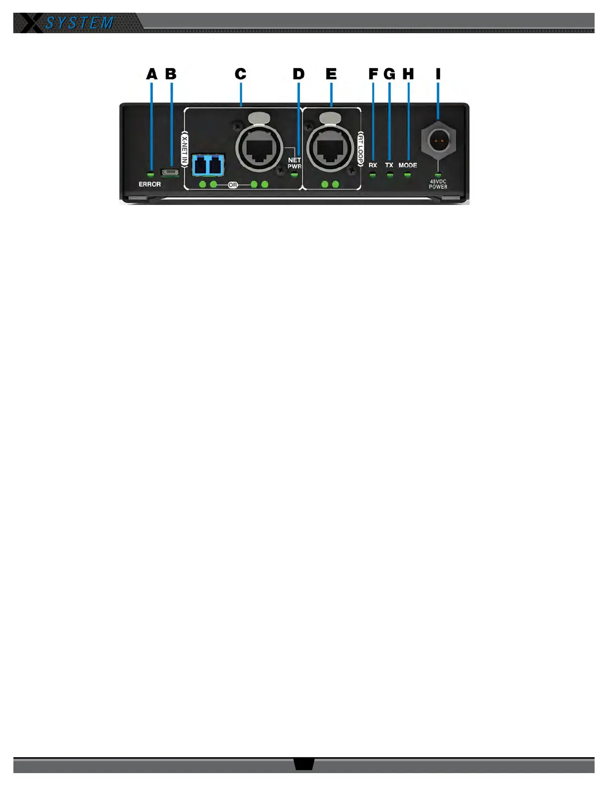
RT Bottom
A. ERROR LED: Indicates the device’s error status.
B. USB Micro B Connection: For connectivity to a PC or Control Unit for updating device rmware.
C. X-NET IN Port (Cat 5e or Fiber): The RT’s X-NET IN ports allow it to connect to any available X-Net port or
RT Loop port on other devices, adding the RT to a proprietary network where all devices are part of a system
conguration that shares data, timing synchronization, and audio. Each RT has an X-NET IN port (RJ-45 for Cat 5e
copper or duplex LC for Single Mode Fiber) and an RT LOOP port (RJ-45, which allows RTs to be daisy-chained to
one another).
D. Network Power (NET PWR) LED: Not currently used with X-System
E. RT LOOP Port and Status LEDs: Not currently used with X-System
F. RX LED: Green LED—BLINKS when RT is receiving transmissions from Radio Packs.
G. TX LED: Green LED—ON (blinking rapidly) when RT is transmitting properly.
H. MODE LED: Green LED—ON when set to Normal Mode.
I. 48VDC POWER Connection and LED: The locking DC Power Connector enables the RT to be powered locally with
a CoachComm 48VDC power supply (sold separately). Not currently used with X-System.
Figure 43: Radio Transceiver Bottom View