OPERATING MANUAL
800.749.2761 www.coachcomm.com
19
Drive System Overview
This section is a basic reference for using your X-System sideline cart’s drive system.
CAUTION: Allow only responsible, authorized individuals who have read all of the instructions and
warnings to operate and drive the cart. CoachComm recommends using a separate spotter
when driving the cart.
Brake
The sideline cart drive system uses a magnetic brake, which acts as a wheel brake and parking brake when the drive
system throttle is not in use. Even with no power to the cart, the brake is engaged.
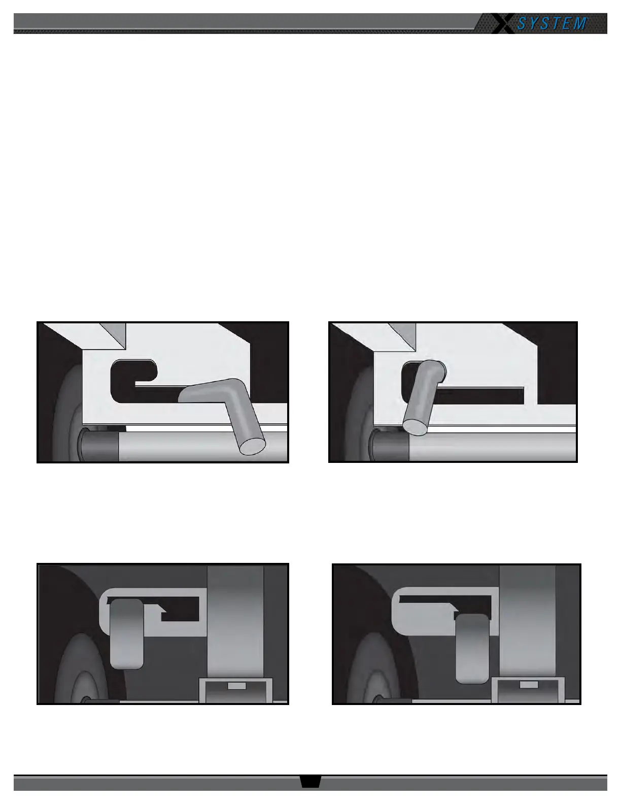
• When using the cart’s drive system, the brake lever (located between the wheels on the side opposite the tow
handle) should be in Position A (Figure 20).
• In the event of a loss of battery power or another issue with the drive system, the cart can be manually towed. In
this case, the brake lever should be in Position B (Figure 21), and the cart should be towed at a maximum speed of
3 mph. Higher speeds may cause a tip hazard or damage to the electric drive system.
Note: Second-generation model X-System carts (those with a black top) have a different brake lever than
rst-generation carts (those with a silver top). See Figure 22 and Figure 23 below.
First-Generation Cart - Position A
First-Generation Cart - Position B
Figure 20: First-Generation Cart Brake Lever Position for Drive System Operation Figure 21: First-Generation Cart Brake Lever Position for Manual Towing
Figure 22: Second-Generation Cart Brake Lever Position for Drive System Operation
Second-Generation Cart Position A
Second-Generation Cart Position B
Figure 23: Second-Generation Cart Brake Lever Position for Manual Towing