OPERATING MANUAL
800.749.2761 www.coachcomm.com
11
Game Day Setup
The procedures in this section serve as a reference for a typical game day setup. You can nd more in-depth information
about the devices and processes mentioned here in later sections of this Operating Manual.
Note: If you are setting up a Wireless Press Box Unit, additional Game Day Setup instructions are provided in
this document’s Appendix starting on page 93.
Getting Started
This Game Day Guide is a basic reference for setting up your X-System. For complete operation instructions, see the rest of
this manual.
CAUTION: Allow only responsible, authorized individuals who have read all of the instructions and warnings to set up
and operate your X-System.
Provided Tools:
• 1/2” socket wrench
• Drill bit adapter (1/4” hex to 1/2” square) for use with any 1/4” drill or cordless
screwdriver
Additional Tools You May Need:
• 1/4” drill or cordless screwdriver
Required Power Connection:
• Minimum of one dedicated 15 amp 120V circuit
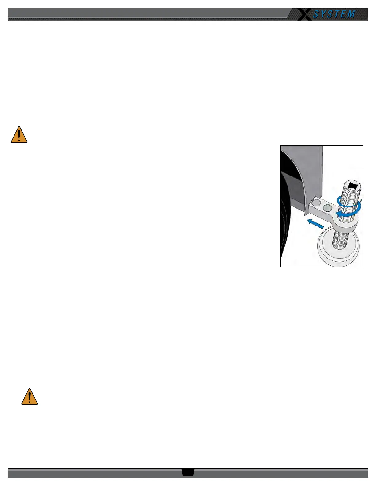
1. Position and stabilize cart.
1a. Once the Cart is positioned at mideld, insert each of the four stabilizers into
their associated slots.
1b. Extend the stabilizers to the ground using either the socket wrench or the drill bit
adapter and drill. Continue extending until stabilizers have made sufcient ground contact to stabilize the cart.
Note: The cart stabilizers are not intended to lift the cart.
2. Prepare RT Mast
Note: The following steps are referenced in Figure 11 and should be performed with at least two people.
2a. Remove the mast from its storage area and insert it into the locked and upright mast receiving tube.
2b. Align the mast so your RT mounting bracket(s) (when attached) will be parallel to the sideline and secure the
mast with pin 1 at the bottom of the tube.
2c. Secure the mast and tube with one hand, then remove pins 2 and 3 from the top of the tube. Carefully lower
the mast to a bench or chair level with the cart. (See Figure 90 on page 65 for a detailed drawing of these pin
locations.)
CAUTION:
Ensure there is a minimum of 20 feet of clearance beside the Cart before lowering the mast.
2d. Extend the mast to the desired height, locking each section in place as you go. (A minimum of 12 feet is
recommended.)
2e. If you are not fully extending the mast, align the index holes of the non-extended sections and secure by inserting
pin 4. This prevents the mast from rotating while extended. (See Figure 90 on page 65 for drawing of pin
locations.)
Figure 10: Sideline Cart Stabilizer