To install the EXPLORER 8000 series
98-145510-E Chapter 3: Installation 3-4
The mounting frame of the antenna has lengthwise adjustable brackets to accommodate
different placements of the supports. If you are not using a roof rack, omit the U-bars.
Roof-rack mount
We recommend a 3-bar solution over a 2-bar solution whenever possible. Adhere to the
load limits of the roof-rack manufacturer and use sturdy, professional grade racks.
Custom made structure
Custom structures should likewise focus on supporting the azimuth base.
Avoid large amounts of magnetizable material close to the antenna - it could adversely
affect the magnetometer. If in doubt, make a test setup prior to final manufacture of the
supporting structure.
For measures for antenna installation, see Measures for antenna installation on page A-14.
See also Weights and measures on page A-3 and Antenna dimensions on page A-12.
3.2.3 Installation of the ACU
To install the ACU, do as follows:
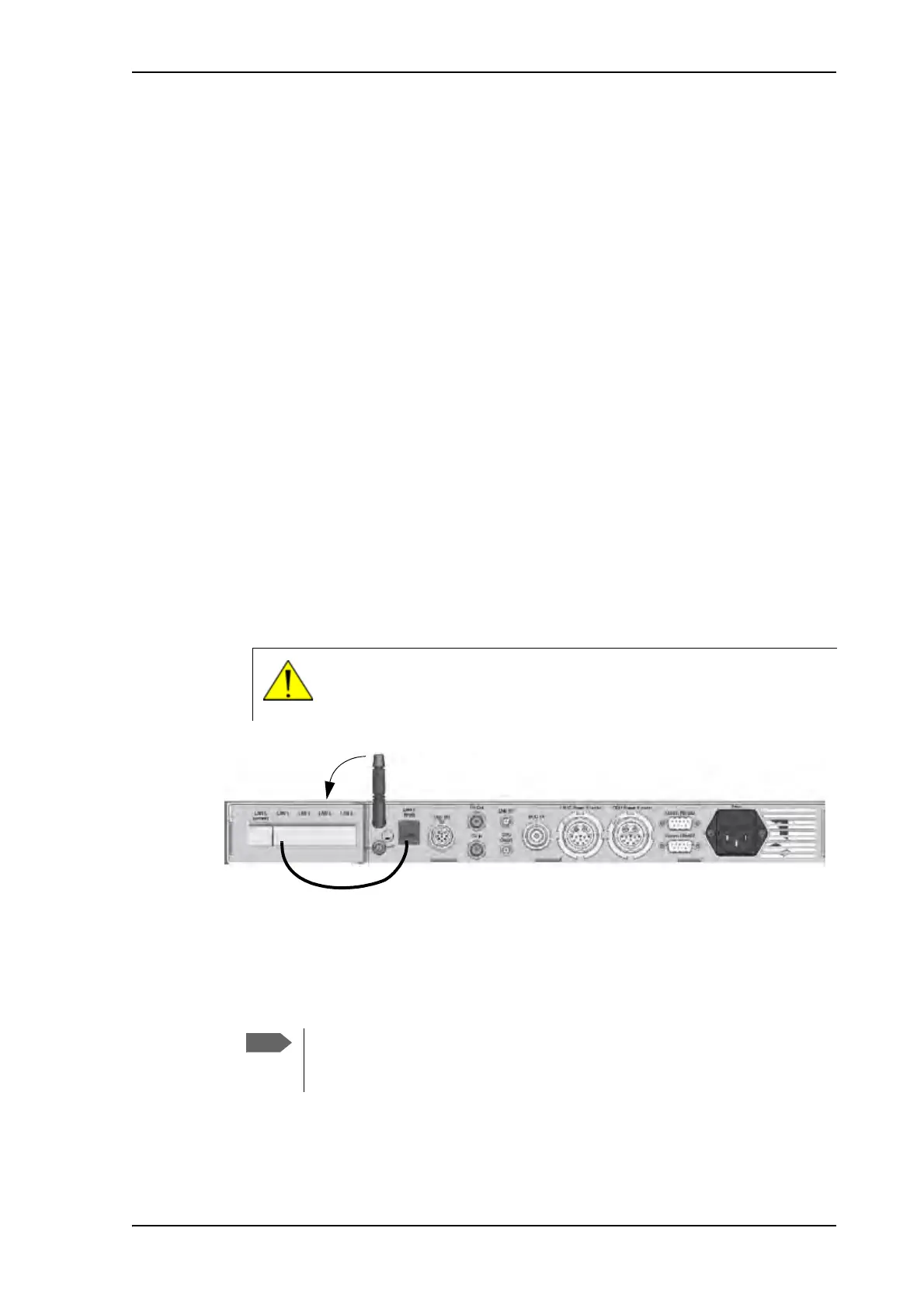
1. If you are going to use WLAN, connect the WLAN antenna to the connector marked
WLAN in the ACU connector panel. The WLAN antenna is part of the accessories
supplied with the EXPLORER 8000 series system.
2. If you are going to use the LAN connector on the front, connect the enclosed patch
cable (37-206570-025) between LAN1 and LANX (Front) on the rear of the ACU.
3. Slide the ACU into a 1U space in a 19” rack.
4. Mount the screws on each side through the holes in the front and fasten the screws to
the rack. Make sure that the unit is mounted securely according to the requirements for
your 19” rack.
CAUTION! Turn the WLAN antenna into horizontal position before
sliding the unit into the rack. The WLAN antenna may be damaged if it is
placed in a vertical position.
Figure 2: ACU connector panel with WLAN antenna
We recommend supporting the ACU either with rails on the side of the rack
system or by attaching it with screws on the side using the 2 M4 inserts on
each side of the ACU (see ACU left and right side on page A-20).