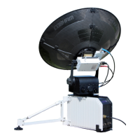
HGA-7001
Installation Manual
Document: 862-A0089_IM issue 1.6
COMPANY CONFIDENTIAL
Page 4 of 45
L
IST OF FIGURES
P
AGE
Figure 1: ARINC 781 SATCOM System Block Diagram ............................................................................ 10
Figure 2: Top Side of Antenna ............................................................................................................. 15
Figure 3: Multi-pin Connector Pin Numbers........................................................................................... 15
Figure 4: HGA-7001 High Gain Antenna Connector Locations (positions relative to the hole in fuselage and
the hole size are typical) ............................................................................................................... 18
Figure 5: HGA Interfaces .................................................................................................................... 19
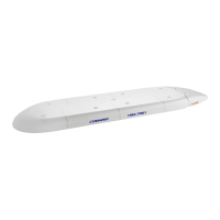
Figure 6: HGA-7001 High Gain Antenna [IPL 18-1] ................................................................................ 22
Figure 7: HGA-7001 Tail Cap [IPL 18-5] ................................................................................................ 23
Figure 8: HGA-7001 Tail Cap Screws [IPL 18-30] .................................................................................. 23
Figure 9: Mounting Hole Sealing Kit [IPL 18-15] ................................................................................... 23
Figure 10: RF Blockage Caused By Aircraft Wing ................................................................................... 26
Figure 11: Grounding Screw Holes, Ground Stud and Bonding Points ...................................................... 29
Figure 12: Cables Connected ............................................................................................................... 31
Figure 13: Fitting the Lanyard ............................................................................................................. 32
Figure 14: Tail Cap Installation ............................................................................................................ 32
Figure 15: Fitting of Tail Cap Screws .................................................................................................... 33
Figure 16: Sealant Application to Sealing Cap ....................................................................................... 34
Figure 17: Removing the Tail Cap ........................................................................................................ 35
Figure 18: IPL – HGA-7001 Antenna .................................................................................................... 43
Figure 19: IPL – Lanyard Assembly ...................................................................................................... 44
Figure 20: IPL – Mounting Hole Sealing Kit ........................................................................................... 45
LIST OF TABLES
P
AGE
Table 1: HGA-7001 Equivalent Part Numbers .......................................................................................... 6
Table 2: Equipment Covered ............................................................................................................... 11
Table 3: Associated Equipment ........................................................................................................... 11
Table 4: Related Publications .............................................................................................................. 11
Table 5: Equipment Specifications (Sheet 1 of 3) .................................................................................. 12
Table 6: Equipment Specifications (Sheet 2 of 3) .................................................................................. 13
Table 7: Equipment Specifications (Sheet 3 of 3) .................................................................................. 14
Table 8: Connector Pin Assignments .................................................................................................... 16
Table 9: Packing List .......................................................................................................................... 22
Table 10: Installation Tools, Fixtures and Equipment ............................................................................. 38
 Loading...


