2-3
Installation
Chapter 2: Installation
98-144591-D
Mounting the Units
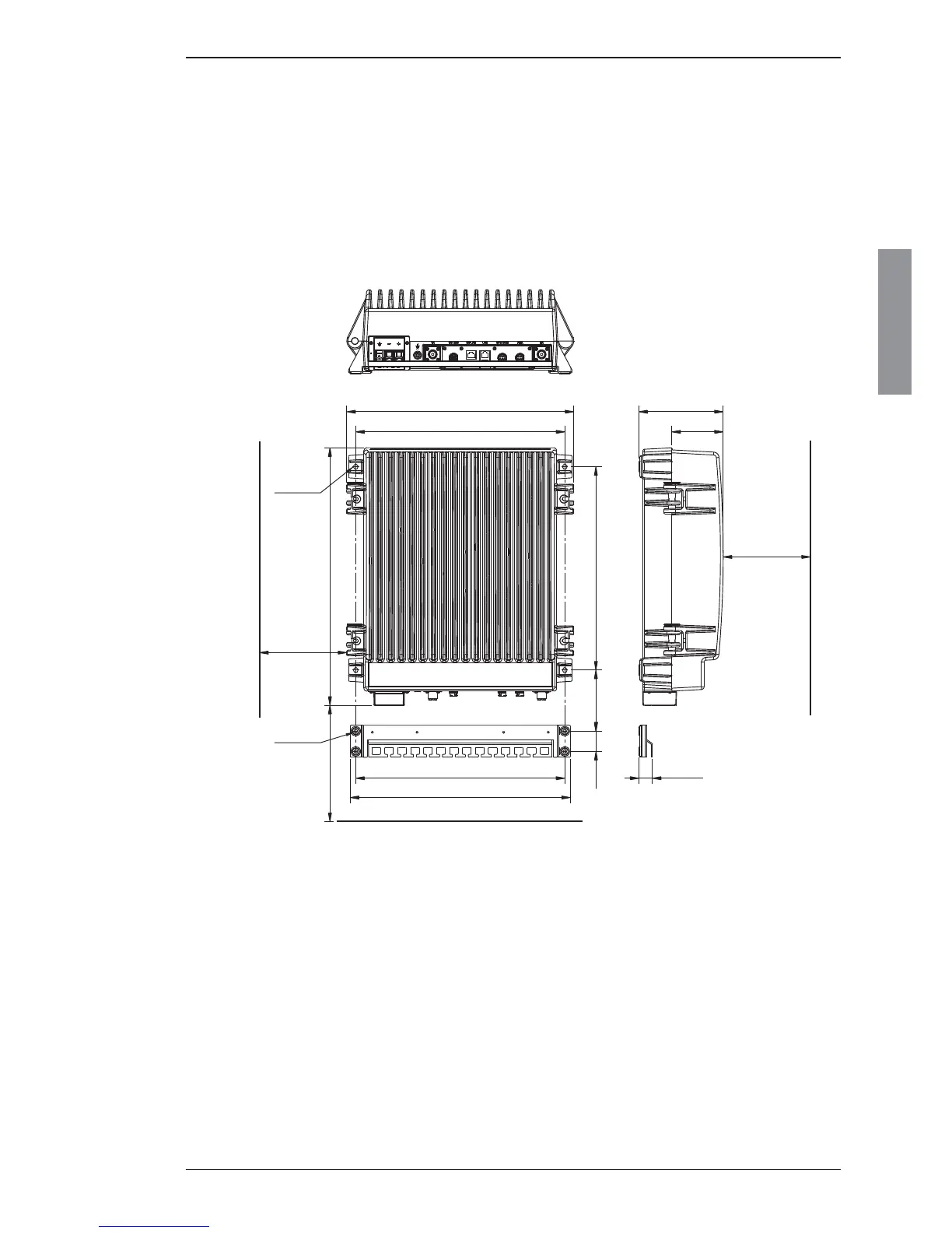
2.2.2 Mounting the Transceiver Unit (TU)
The Transceiver Unit should be installed in a dry place and consideration should be given to acces-
sibility for servicing. It is important to provide suffi cient airspace below, above and in front of the unit
for adequate air circulation through the cooling fi ns. The drawing below shows the outer dimensions,
mounting possibilities and the minimum distance to other objects, as well as a drilling plan.
Transceiver Unit 150 W/250 W
105 mm 350 mm
360 mm
391 mm
35 mm
150 mmMin.
379 mm
150 mmMin.
360 mm
Space for
cable access
Space for
service
4 x ø8mm
443 mm
4 x ø6mm
23.5 mm
88 mm
145 mm
500Min. mm
Space for airflow
and service
 Loading...