2-21
Installation
Chapter 2: Installation
98-144591-D
Interconnection of units
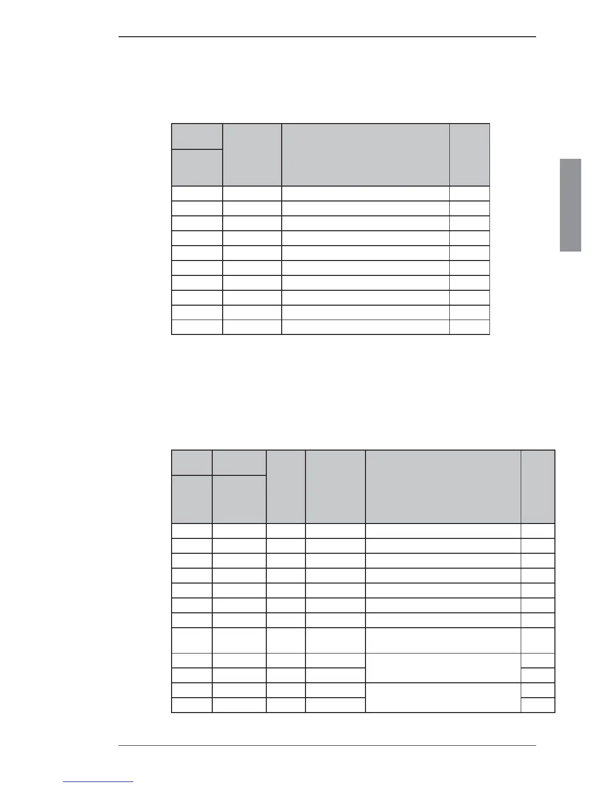
Cable 1: Control Unit - ACC
Cable: 10 x LTW-UL2464 26AWG
Cable-connector: 10 way (ex. LTW)
5 m cable with connector supplied
Control
Unit
Designation Remarks Color
'ACC'
10 way
LTW
1 NMEA+ NMEA position input Brown
2 NMEA- NMEA position input Blue
3 2182 Select OC output. Low when 2182 kHz is selected White
4 NC No Connection Green
5 MIC Handset microphone Yellow
6 EAR Handset earpiece Grey
7 HOOK PTT Hook and PTT Pink
8 +12 V DC 12 V supply to handset Red
9 GND System ground Black
10 GND System ground Orange
Cable 2: Control Unit - Ground
Recommended wire dimension: min. 2.5 mm
2
(AWG 13) - Maximum length 0.2 m
Cable 3: Control Unit - Transceiver Unit
Cable: 12 x LTW-UL2464 20AWG
Cable-connector: 12 way (ex. LTW)
6 m cable with connectors supplied with equipment
Control
Unit
Transceiver
Unit
Tvisted
pair
Designation Remarks Color
'TU-CU
BUS'
12 way
LTW
'TU-CU
BUS'
12 way
LTW
1 1 a SHIELD Screen connected to system ground Brown
2 2 b GND System ground Blue
3 3 b +24 V Supply voltage for the Control Unit White
4 4 c CAN Vcc CAN supply (15 V DC) Green
5 5 d CAN H CAN data H Yellow
6 6 d CAN L CAN data L Grey
7 7 c CAN GND CAN ground Pink
8 8 a SUPPLY_ON
Supply on signal to the Transceiver Unit
Active when connected to GND
Red
9 9 e AUDIO IN+
Balanced Audio IN
Black
10 10 e AUDIO IN- Orange
11 11 f AUDIO OUT+
Balanced Audio OUT
Violet
12 12 f AUDIO OUT- Cyan
 Loading...