2-22
Chapter 2: Installation
98-144591-D
Interconnection of units
Cable 3a: 2nd Control Unit - Transceiver Unit
If a 2nd control unit is installed, this can be done by splitting and extending the CAN bus, using e.g.
the 406208A control unit box.
Note that the CAN bus must be terminated with 120 Ohm in each end of the bus (not in the middle!).
The transceiver unit is terminated per default. Move Jumper W402 placed just inside the transceiver
unit, if termination is not needed in the place the transceiver is installed. In this case, termination
must added at both control units.
Cable 4: Transceiver Unit - TX Antenna
Cable: 50 ohm coaxial cable RG213/U (or better)
Maximum cable length 100 m
Cable-connector: UHF connector PL259, Crimp type connector should be used.
Cable 5: Transceiver Unit - Ground
Recommended wire dimension: min. 10 mm
2
(AWG 7)
Maximum length 0.2 m
Cable 6: Transceiver Unit - RX Antenna
Type: 50 ohm coaxial cable RG213/U (or better)
Maximum cable length 100 m
Cable-connector: UHF connector PL259, Crimp type connector should be used.
Cable 7: Antenna Tuning Unit - Ground
Copper strap 100 x 0.5 mm or 3 x 25mm
2
(AWG 3) shielded cable with wires and shielding connected
to ATU GND and shielding left open at the other end.
Refer to section ‘Ground Connections’
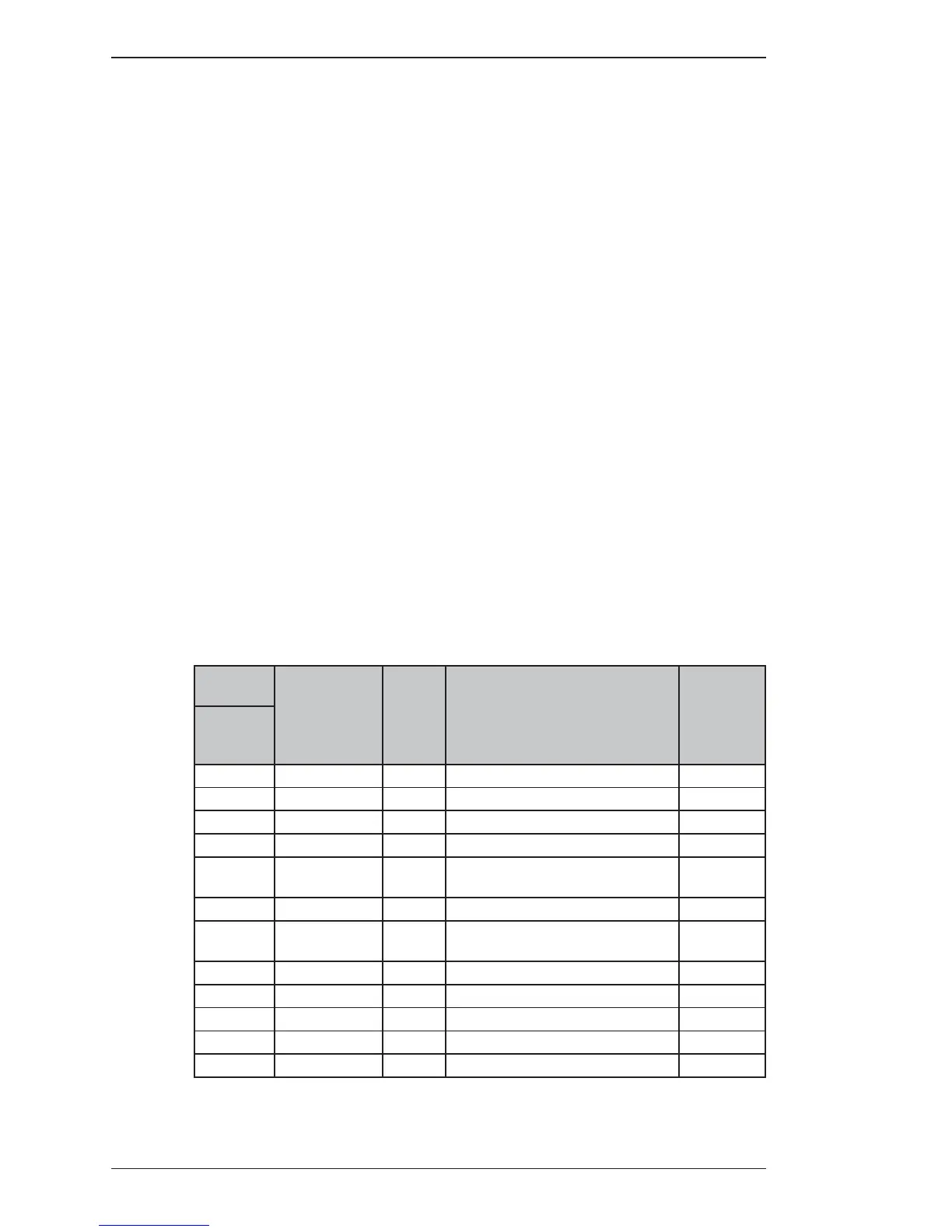
Cable 8: Control Unit – AUX
Cable: 12 x LTW-UL2464 20AWG
Cable-connector: 12 way (ex. LTW)
6 m cable with connector, available from eShop
Control
Unit
Designation
Cable
no.
Remarks Color
'AUX'
12 way
LTW
1 NC 10 No Connection Brown
2 NC 11 No Connection Blue
3 NC 11 No Connection White
4 NC 9 No Connection Green
5
OTHER DSC
ALARM
8 + 5 V Logic Level output, when active Yellow
6 NC 10 No Connection Grey
7 DISTRESS
ALARM
10 + 5 V Logic Level output, when active Pink
8 GND 9 System ground Red
9 SPEAKER OUT 8
External speaker (max. 6W in 8 ohm)
Black
10 NC 10
No Connection
Orange
11 NC 11
No Connection
Violet
12 NC 12
No Connection
Cyan
 Loading...