LS1000 VoIP Speakerphone
Administrator Guide
page 47 of 54 GU-164-B
Code Blue
• 259 Hedcor Street • Holland, MI 49423 USA • 800.205.7186 • www.codeblue.com
All wiring must be installed and connected by experienced and certified personnel to meet local
and national electrical codes, and will include a service disconnect.
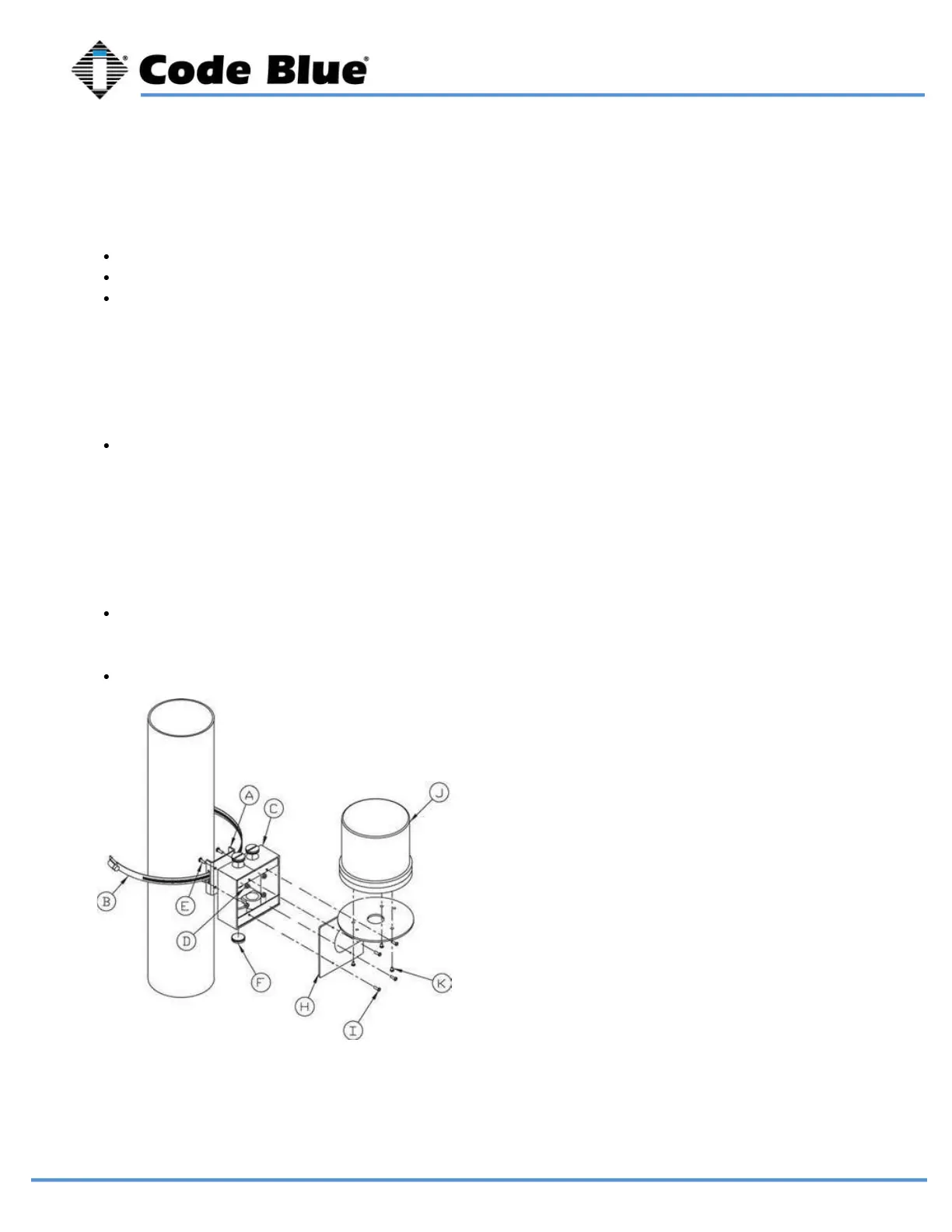
15 Remote Mount Beacon/Strobe Installation
A - pole-bracket
B - banding
C - J-box
D - pole-bracket mount nut (4 each)
E - pole-bracket mount screw (4 each)
F - conduit plug
H - strobe-bracket I - 6-32 X ½ screws (4 each)
J - strobe light
K - M4 X 8 screws (3 each) (Low voltage)
K - 10-24 X ¾ screws (2 each) (High voltage)
Thread the banding (B) through the pole bracket (A) located on the backside of the J-box (C).
Wrap the banding around the pole. Cut the banding to desired length.
Using a screwdriver or nut driver, tighten the banding and make sure that the unit is in the
desired location.
Using the three M4 X 8 screws enclosed (K), fasten the strobe (J) to the round portion of the
strobe bracket.
Connect all wiring from the strobe to the wiring from the unit inside of the J-box using wire
nuts.
Attach strobe bracket to the J-box using four 6-32 X ½ screws as shown
ATTACH J-BOX TO THE POLE
NOTE: J-box must be positioned so weep hole faces down.
ATTACH LIGHT TO BRACKET
NOTE: If the beacon/strobe is mounted upside-down, a drain hole must be drilled into the lens to
prevent it from filling with water.
ATTACH LIGHT AND BRACKET TO THE J-BOX