13
MACHINE PREPARATION
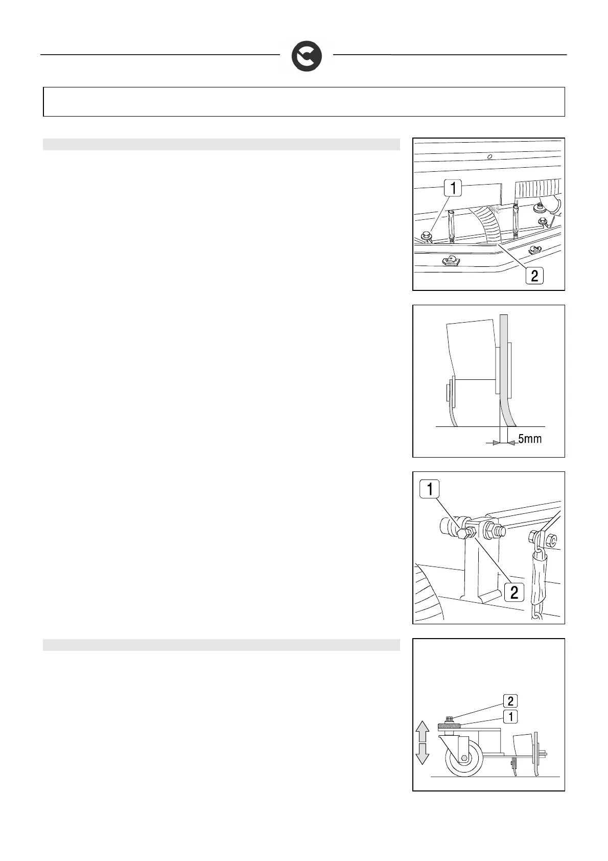
7. SQUEEGEE
For packaging reasons, the squeegee is supplied disassembled. It must be assembled as
shown in the figure, inserting its screws (1) in the special housings on the squeegee support
and fixing it with a CH17 spanner.
Insert the suction tube (2) in the sleeve and fix it with the special clamp.
During working operation, the rear rubber is slightly tilted backwards (by about 5mm) in a
uniform way for its whole length.
If it is necessary to increase the bend of the rubber in the central part, you must tilt the
squeegee backwards, loosening the locknut (2) and turning the screw (1) anticlockwise. To
increase the bend of the rubber at the sides of the squeegee, loosen both the locknut (2) and
the screw (1). When fully adjusted, fix the locknut. These operations can be carried out with the
aid of a CH13 spanner.
8. ADJUSTING THE SQUEEGEE SUPPORT HEIGHT
The height of the squeegee must be adjusted on the basis of the state of wear and tear of the
rubber. Proceed as follows:
1. loosen the ring nut (1)
2. use a CH17 spanner to turn the pivoting wheel, via the nut (2), clockwise to lift the
squeegee and anticlockwise to lower it
3. fix the ring nut (1)
NB: the left and right pivoting wheels must be adjusted to the same height