M0203AHA_uc CommScope ERA
®
CAP M2 with Fiber Interface
© August 2022 CommScope, Inc. Page 33
Connect the Cables to the Fiber CAP M2
• If the 50 coaxial cable has a push-pull connector, make sure the cable is seated firmly in the
ANT 1, ANT 2, ANT 3 or ANT 4 connector.
• If the 50
coaxial cable has a threaded connector, torque the connector 5 N-m (3.69 ft-lb). Do not
over-tighten the connector.
f Connect the other end of the 50
coaxial cable to the passive antenna installed in Step b.
2 If necessary, repeat Step 1 on page 32 to connect a 50
coaxial cable to the other ANT connector.
Connect the Optical Fiber
Connecting the optical fiber cable from the hybrid splice box requires removing the CAP M2 cover on the
bottom of the AP.
The optical fiber cable may be connected with or without the optional SFP+ module pair.
1 Install the hybrid splice box on the CAP M2 bracket. See "Mounting a CAP M2 with a Hybrid Fiber Splice
Box Kit (optional)” on page 22.
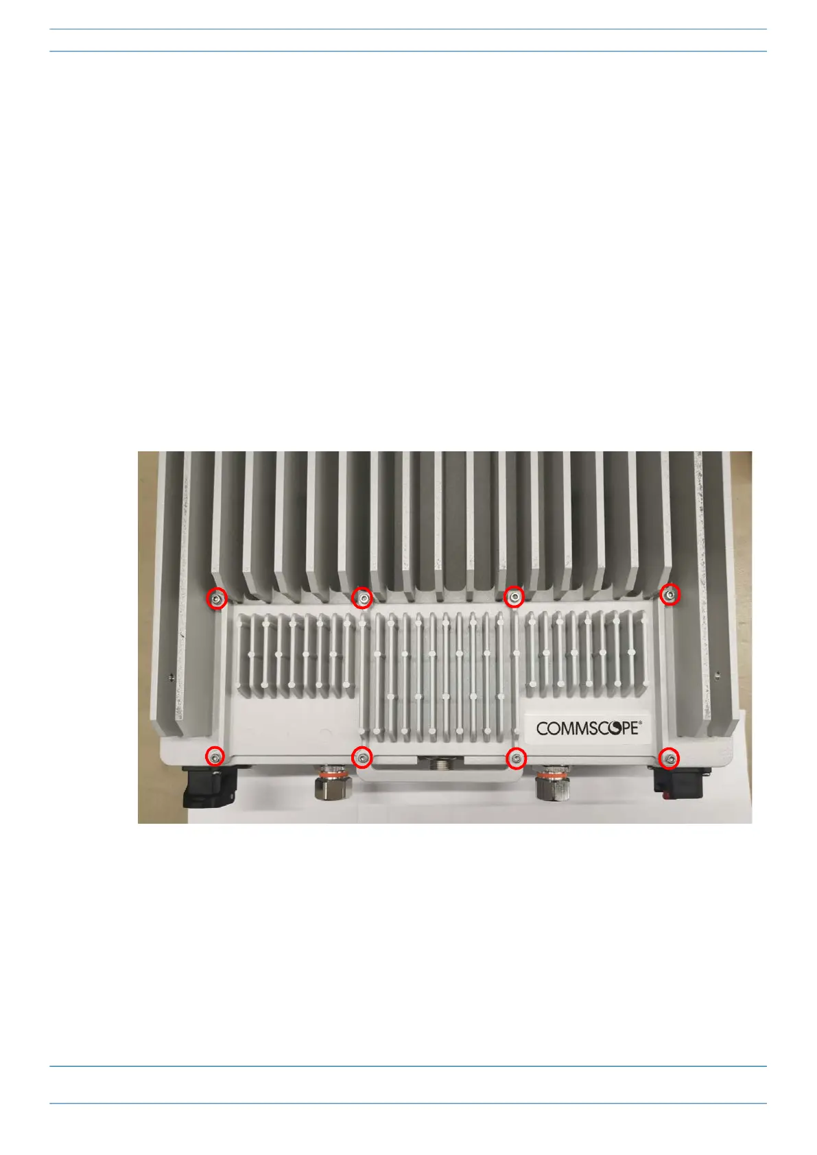
2 Loosen the eight torque screws on the cover located at the bottom of the CAP M2.
3 Feed the cable from the hybrid splice box through the CAP M2 port, as shown below, and assemble the
OCTIS LC Universal lever and insert it into the CAP M2 port as shown in Figure 2. For OCTIS Universal
connector assembly instructions, see "OCTIS Universal Lever Assembly Instructions” on page 11.