EasyManua.ls Logo

Comnet CNGE2FE8MSPOE User Manual

Comnet CNGE2FE8MSPOE
162 pages
To Next Page IconTo Next Page
Page #1 background imageLoading...
Page #1 background image
INSTALLATION AND OPERATION MANUAL
CNGE2FE8MSPOE
ENVIRONMENTALLY HARDENED MANAGED ETHERNET
SWITCH WITH (8) 10/100TX + (2) 10/100/1000TX RJ45
OR 100/1000 FX SFP PORTS
V1.04 – March 2010
CNGE2FE8MSPOE Managed Ethernet Switch provides transmission of (8)
10/100 BASE-TX and (2) 10/100/1000TX or 100/1000FX combo ports. Unlike
most Ethernet switches, these environmentally hardened units are designed
for deployment in difficult operating environments, and are available for use
with either conventional CAT-5e copper or optical transmission media. The 8
electrical ports support the 10/100 Mbps Ethernet IEEE 802.3 protocol, and
auto-negotiating and auto-MDI/MDIX features are provided for simplicity and
ease of installation. All 8 ports support IEEE.802.3af based POE. 2 ports are
10/100/1000 configurable for copper or fiber media for use with multimode
or single mode optical fiber, selected by optional SFP modules. These
network managed layer 2 switches are optically (100/1000 BASE-FX) and
electrically compatible with any IEEE 802.3 compliant Ethernet devices. Plug-
and-play design ensures ease of installation, and no electrical or optical
adjustments are ever required. The CNGE2FE8MSPOE incorporates LED
indicators for monitoring the operating status of the managed switch and
network.

Table of Contents

Question and Answer IconNeed help?

Do you have a question about the Comnet CNGE2FE8MSPOE and is the answer not in the manual?

Comnet CNGE2FE8MSPOE Specifications

General IconGeneral
PoE StandardsIEEE 802.3af/at
PoE Power Budget120W
MAC Address Table8K
Ports2 x 100/1000Base-X SFP ports
Operating Temperature-40°C to 75°C
InstallationDIN-Rail mounting

Summary

Chapter 1 Introduction

1.1 Hardware Features

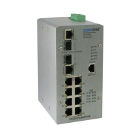
Details the physical and standard capabilities of the industrial switch.

1.2 Software Features

Details the management, protocols, and software features supported by the switch.

Chapter 3 Hardware Installation

3.1 Installation Steps

Provides a step-by-step guide for unpacking, mounting, and connecting the switch.

3.4 Wiring the Power Inputs

Explains the procedure for connecting DC power wires to the terminal block.

3.6 Cabling

Offers guidelines for selecting and connecting Ethernet and fiber optic cables.

Chapter 4 Network Application

4.1 X-Ring Application

Illustrates the X-Ring protocol for fast network recovery and redundancy.

Chapter 5 Console Management

5.3 Console Login Procedure

Explains terminal emulation setup and login procedure for the console interface.

Chapter 6 Web-Based Management

Appendix B—Command Sets

Related product manuals