122
Appendix A—RJ45 Pin Assignment
RJ45 Pin Assignments
The UTP/STP ports will automatically sense for Fast Ethernet (10Base-T/100Base-TX
connections), or Gigabit Ethernet (10Base-T/100Base-TX/1000Base-T connections). Auto
MDI/MDIX means that the switch can connect to another switch or workstation without
changing straight through or crossover cabling. See the figures below for straight through
and crossover cable schematic.
10 /100BASE-TX Pin outs
With10/100BASE-TX cable, pins 1 and 2 are used for transmitting data, and pins 3 and 6
for receiving data.
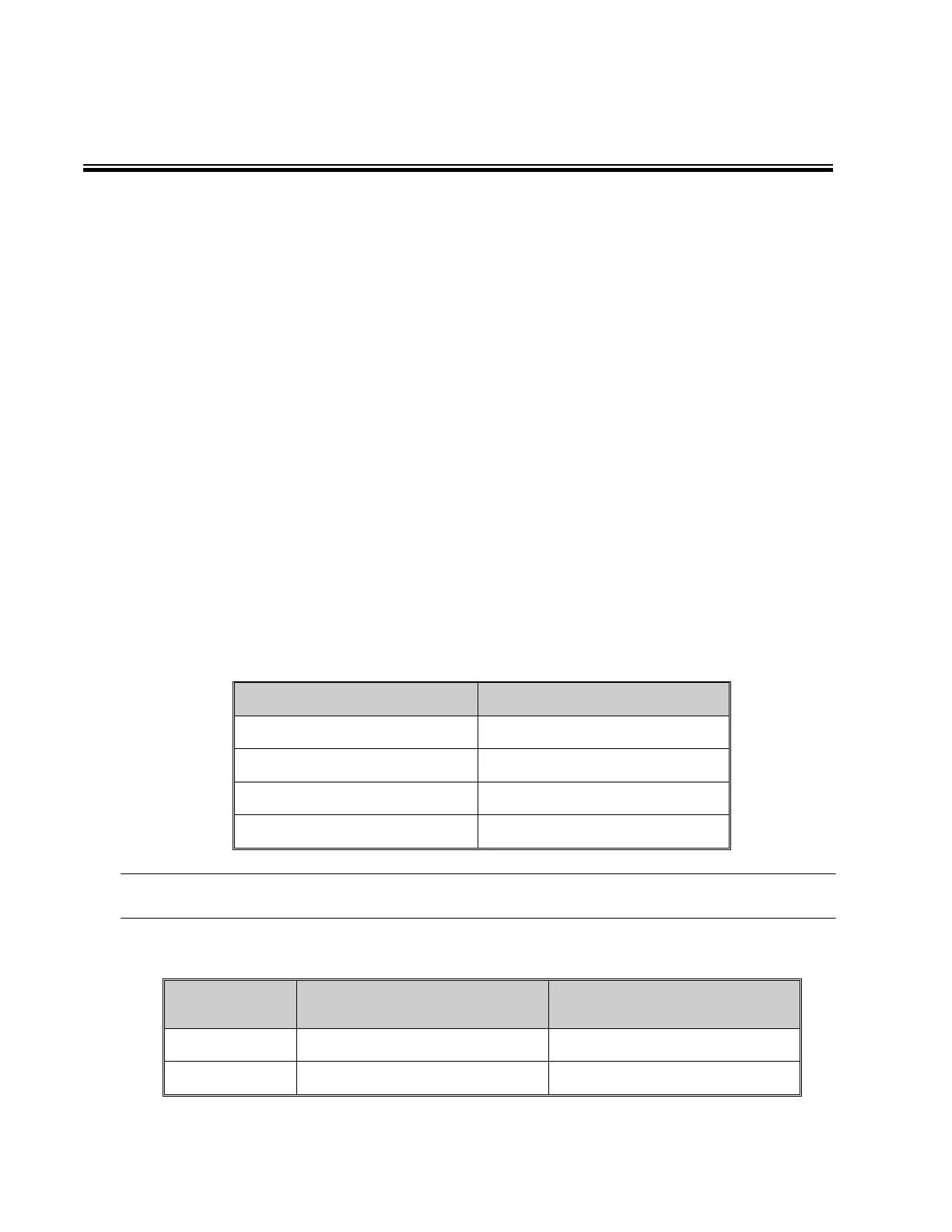
RJ45 Pin Assignments
[NOTE] “+” and “-” signs represent the polarity of the wires that make up each wire pair.
The table below shows the 10/100BASE-TX MDI and MDI-X port pin outs.