Use medium threadlock on all
screws threaded into metal
parts.
Verwenden Sie auf allen
Schrauben die in Metallteile
geschraubt werden mittelfeste
Schraubensicherung.
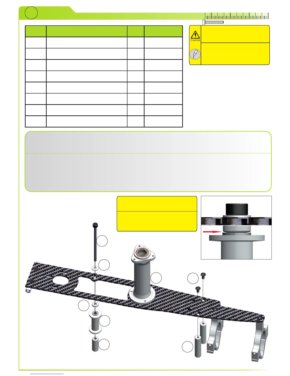
Mount rear guide wheel spacers (5) with bolts (8) to cf plate from STEP24 (1).
Slide bolt (6) through washer (7), cf plate (1), upper spacer (3), guidewheel (2) and lower spacer (4).
When
mounting spacers (5) wrap cotton cloth on the jaws of pliers - this will prevent scratches on spacers.
Montieren Sie die hinteren Abstandshalter für die Führungsrollen (5) mit den Schrauben (8) an die CFK Platte
aus STEP24 (1).
Schieben Sie die Schraube (6) durch die Scheibe (7), CFK Platte (1), den oberen Abstandshalter (3), die
Führungsrolle (2) und den unteren Abstandshalter (4).
Verwenden Sie eine Zange und etwas Baumwolltuch oder ähnliches um den Abstandshalter (5) bei der
Montage zu halten.
1
2
3
4
5
6
7
8
Angled side of spacers should
always face to bearing!
Die Abgeschrägte Seite der Spacer
sollte immer in Richtung Lager
montiert sein.
Page 25