51ConMet
11. Hub and Rotor Removal and Disc Replacement
HAZARD ALERT
MESSAGES
Read and observe all hazard alert
messages in this publication. They
provide information that can help
prevent serious personal injury,
damage to components, or both.
Do not work under a vehicle supported only by
jacks. Jacks can slip and fall over. Serious personal
injury and damage to components can result.
Park the vehicle on a level surface. Block the
wheels to prevent the vehicle from moving.
To prevent serious eye injury, always wear
safe eye protection when you perform vehicle
maintenance or service.
WARNING
!
HUB AND ROTOR
REMOVAL
1. Lift the axle and support it
with safety stands. Refer to
the vehicle manufacturer's
recommended instructions.
2. Remove the tires and wheels.
3. Remove the hubcap or
drive axle. Refer to the
manufacturer's recommended
instructions.
4. Follow the brake manufacturer's
instructions to remove the brake
caliper and brake pads from
the axle mounting point.
Do not loosen the axle spindle nuts by either
striking them directly with a hammer, or striking
a drift or chisel placed against them. Damage to
the parts will occur causing possible loss of axle
wheel-end components and serious personal
injury.
WARNING
!
5. Remove the spindle nut
assembly.
Refer to Conventional, PreSet and PreSet Plus hub
removal procedures in this manual for specic
spindle nut removal instructions.
NOTE
6. Slide the hub and rotor
assembly off the spindle. Be
careful not to damage the outer
bearing.
7. Remove the bolts that secure
the rotor to the hub. Be careful
not to damage the ABS tone
ring when the rotor is removed.
8. Remove the seal from the hub.
9. Clean the bearing cups and
cones, bearing spacer, grease
cavity, and seal bore of the hub.
10. Inspect all components for
signs of wear or damage.
Replace components as
necessary.
11. Clean the spindle. It may
be necessary to remove the
inner portion of the seal from
the spindle. If necessary, use
emery cloth to remove rust and
foreign material from the seal
journal on the spindle.
12. Clean the rotor mounting area
of the hub.
DISC BRAKE ROTOR
REPLACEMENT
Do not hit steel parts with a steel hammer. Pieces
of a part can break o. Serious personal injury and
damage to components can result. Use a brass or
synthetic mallet for assembly and disassembly
procedures.
WARNING
!
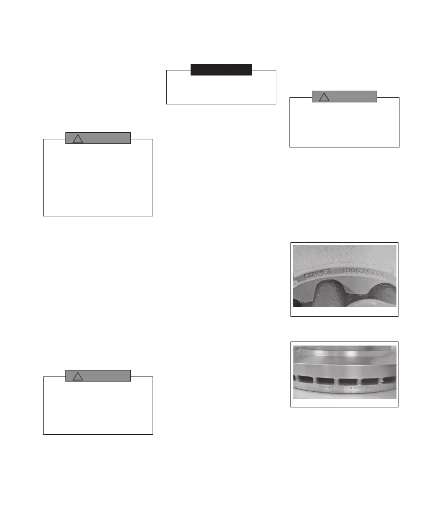
PART IDENTIFICATION
The brake rotor can be identied
by the part number that is cast or
stamped into the rotor. Use the
brake rotor part number to nd the
specic replacement instructions
for the hub and rotor assembly you
are working on (see gures 122
and 123).
106832a
Cast Part Number
FIGURE 122
106848a
Stamped Part Number
FIGURE 123