Commander SE User Guide
50 Issue Number 5
*Commander SE Size 4 >100°C
0 - no autotune
1 - non-rotating static autotune
2 - rotating autotune
There are two levels of autotune that can be performed by the Commander SE.
Non-rotating static autotune
This autotune measures the motor stator resistance and system voltage offset. The
results of the testare storedin the appropriate parameters. After the testis carried out,
the motor will run as requested.
The motor must be at standstill before this test is initiated.
Rotating autotune
The Drive will always carry out a rotating autotune on the motor in the forward
direction or motor rotation even if the run reverse command is given to initiate
the autotune routine.
In addition to the stator resistance and system voltage offset, the rated magnetising
current and total system leakage inductance are measured. The motor is accelerated
up to
2
/
3
rated speed in the forward direction of motor rotation to measure the rated
magnetising current. The speed will be less if insufficient DC Bus voltage is available
to operate at
2
/
3
rated speed without fieldweakening. After this autotune has been
carried out, the run forward or run reverse terminal will need to be opened and closed
to allow the motor to run.
The stator resistance and voltage offset are stored in their appropriate parameters.
The rated magnetising current and total system leakage inductance are used to set up
the motor rated power factor (parameter 09).
The motor must be at standstill and unloaded before this test is initiated.
The main advantage of carrying out a rotating autotune over a non-rotating autotune
is that the Drive calculates the correct power factor, rated torque current and
magnetising current for the motor. This will give more accurate slip compensation (if
enabled).
Autotune Procedure
Before a non-rotating static autotune is carried out, the Drive’s motor map parameters
should be correctly set:
Before a rotating autotune is carried out, additionalparameters should be correctly set
(this is only true if the motor is not a standard 50/60Hz motor).
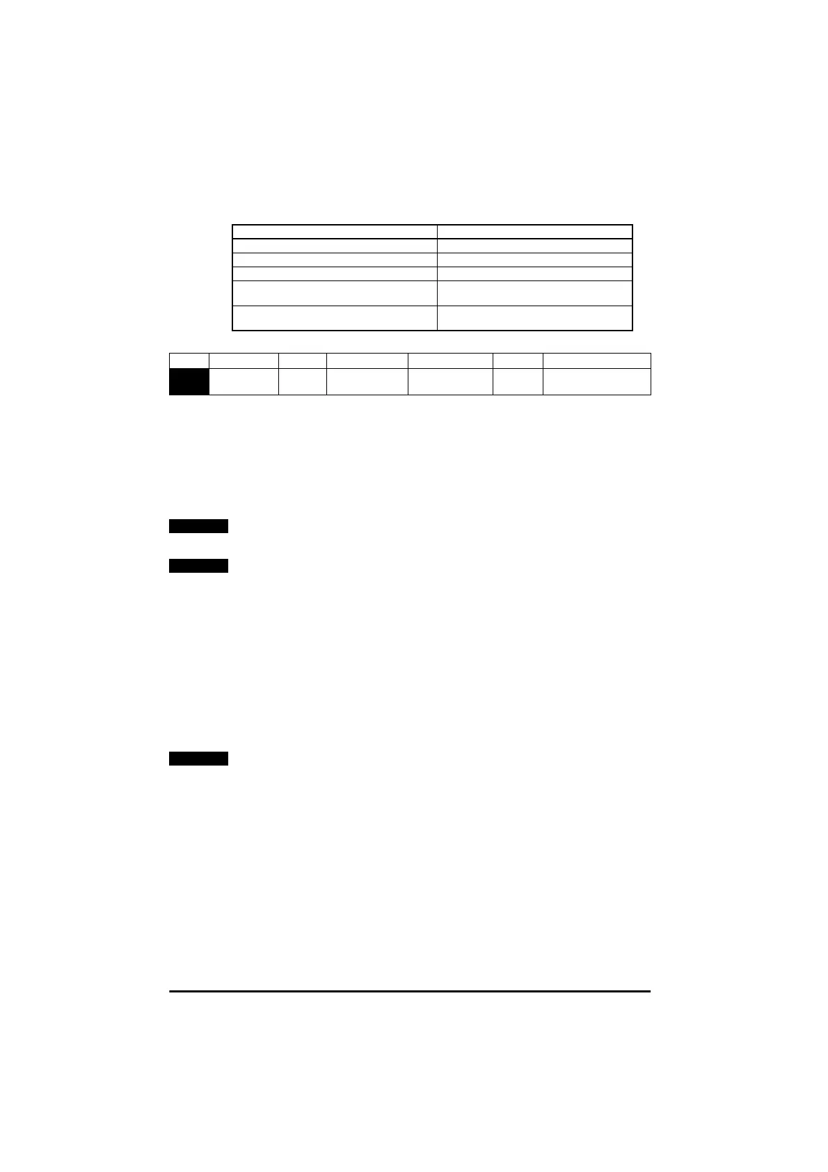
Drive Condition Action
Heatsink >95°C* Trip Drive
Heatsink >92°C Reduce switching frequency to 3kHz
Heatsink >88°C Reduce switching frequency to 6kHz
Heatsink <85°C and IGBT temperature at new
switching frequency <135°C
Allow an increase in switching frequency
IGBT temperature >135°C
Reduce switching frequency
If it is already 3kHz, trip Drive
No. Function Type Limitations Range Units Defaults
38
Autotune RW U 0 - 2 0 EUR
0USA
NOTE
NOTE
NOTE
Parameter 06 - motor rated current Parameter 08 - motor rated voltage
Parameter 07 - motor rated speed Parameter 09 - motor power factor
Parameter 39 - motor rated frequency Parameter 02 - maximum speed