Dinverter
A
User Guide
Issue code: d2au9
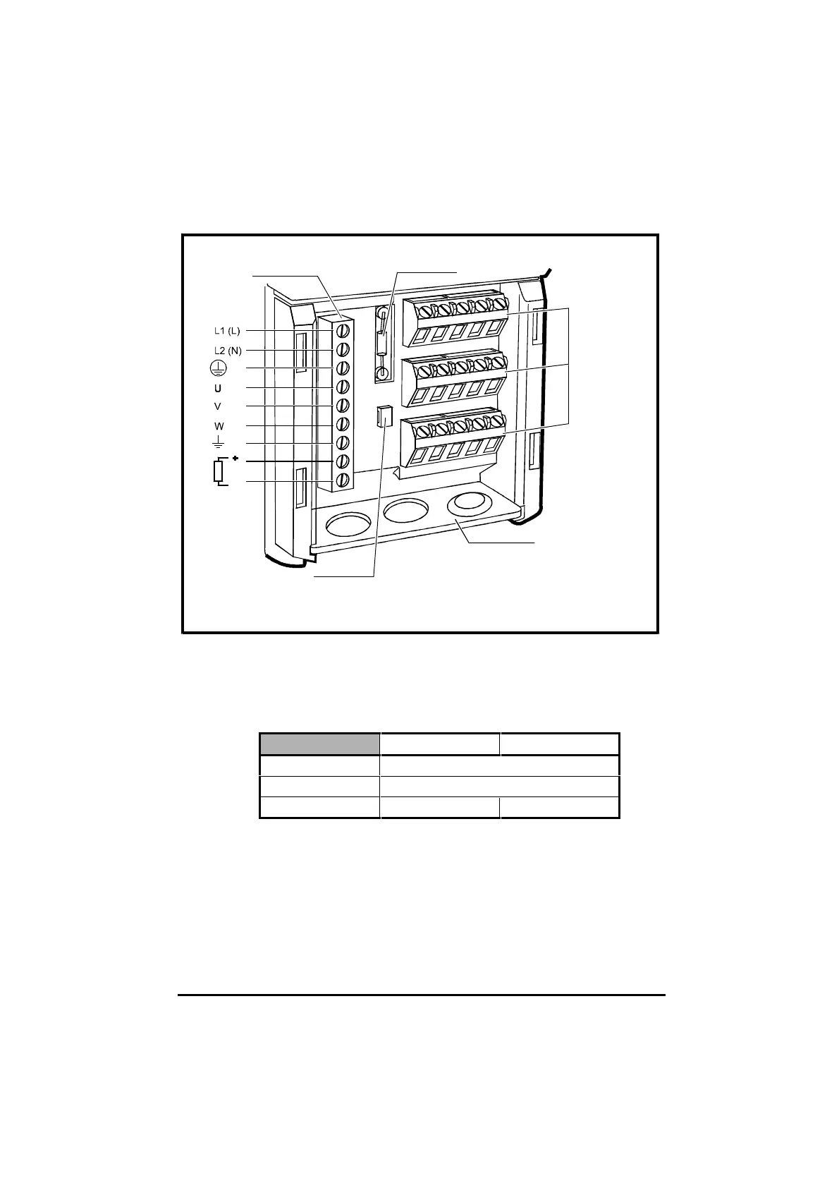
Power
connector
Signal
connectors
Termination
resistor
Gland plate
Cable-tying
point
Figure 4–5 Locations of the power and signal connectors, gland plate,
cable-tying point and termination resistor in the terminal
chamber of the Drive
Table 4–4 Connector sizes and data
Power connector Signal connectors
Maximum wire size 2.5mm
2
(14AWG)
Use screwdriver type... 3mm (
1
/
8
in) flat-blade
Tightening-torque 0.5Nm (4.4 lb.in) 0.4Nm (3.5 lb.in)
2 When the Drive must meet IP20, fit three glands to the gland plate
when the Drive is to be used in Terminal mode; fit two glands when
the Drive is to be used in Keypad mode. (See Methods of control in
Chapter 1 Introduction.)
3 When glands are used, refer to Figure 4–6.