Dinverter
A
User Guide
Issue code: d2au9
If the control signal connections are to be accessible to
personnel, a 0V-common terminal (A1, B1 or C1) must be
connected to a safety ground by a wire which is capable of
carrying the fault current before the AC supply fuse
disconnects the supply. Alternatively, a second isolation
barrier must be used for making signal connections to the
signal connectors.
Caution
The Drive is configured for negative logic. Connecting the
Drive to a positive-logic
PLC could cause the Drive to start
the motor automatically when the AC supply is connected to
the Drive.
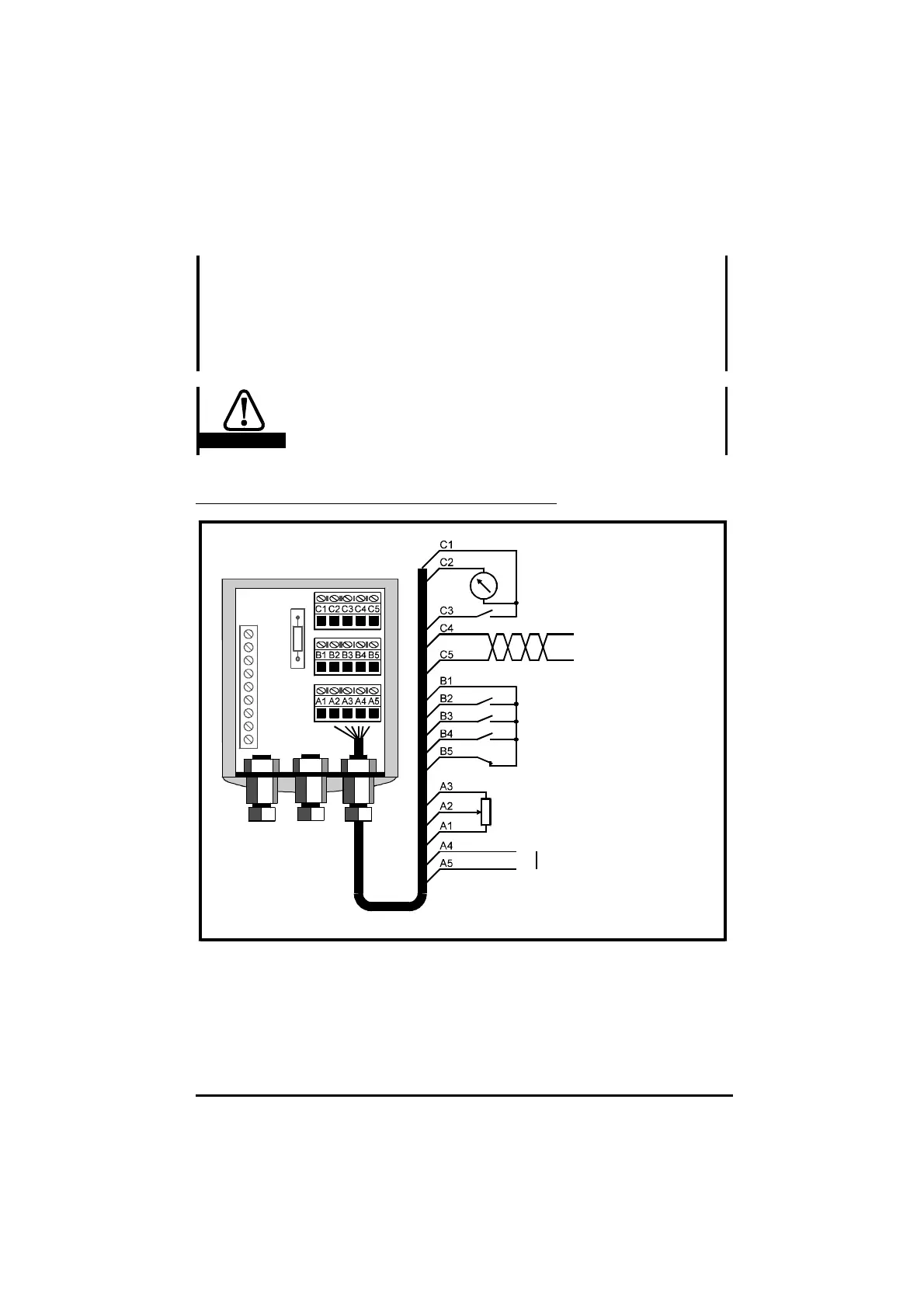
Control signal connections
0V common
LOCAL/REMOTE
SERIAL COMMUNICATIONS
/ ANALOG INPUT 2
RUN FORWARD
RUN REVERSE
DRIVE ENABLE
External trip
ANALOG INPUT 1
Local speed-reference
Relay contact
Closed when the Drive is
operating normally
Open when the Drive is tripped
MOTOR SPEED signal
0V common
+10V
0V common
5kΩ
(2kΩ min)
(Glands fitted
if required)
Figure 4–11 Control signal connections
Analog signal wiring must be shielded unless it is totally contained in the
enclosure. The shield must be grounded at the system controller not at the
Drive-end of the cable.