Dinverter
A
User Guide
Issue code: d2au9
48
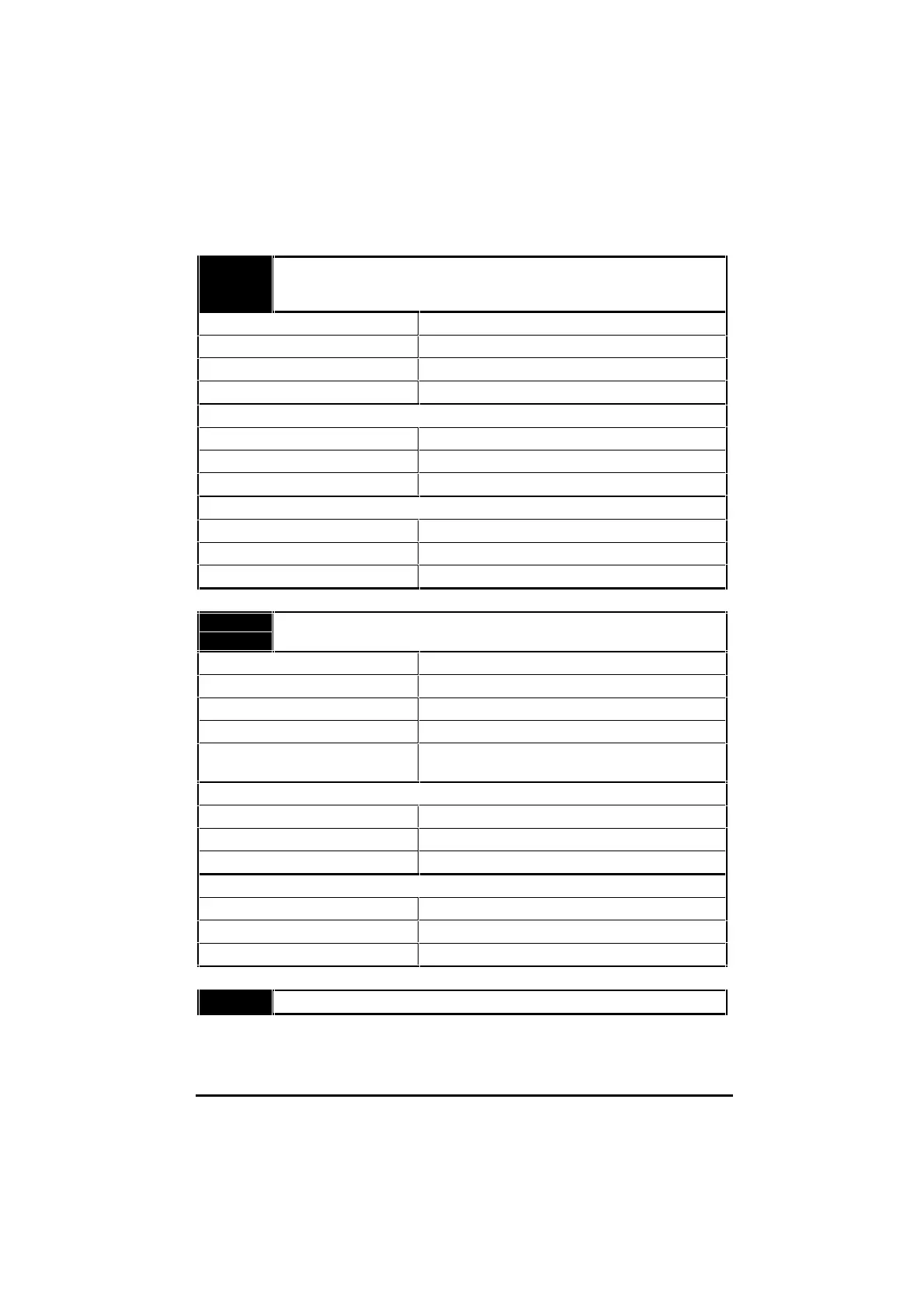
B2B2
B3B3
B4B4
Digital input F3
Digital input F4
Digital input F5
Function Digital control signals
Voltage range 0V to +24V
Absolute maximum voltage range –3V to +30V relative to 0V common
Sampling period 8ms (120Hz)
Switching thresholds when operating in negative logic (default)...
Inactive (logic high) ≥11.1V, or ≥21.2kΩ connected to 0V
Active (logic low) ≤4.4V, or ≤2.6kΩ connected to 0V
Input resistance 5.6kΩ pull-up resistor
Switching thresholds when operating in positive logic...
Active (logic high) ≥11.1V
Inactive (logic low) ≤4.4V
Input resistance 5.6kΩ pull-down resistor
B5B5
C3C3
Digital input/output F1
Digital input/output F2
Function of terminal B5 External-trip input
Function of terminal C3 LOCAL/REMOTE
Voltage range 0V to +24V
Absolute maximum voltage range –3V to +30V relative to 0V common
Sampling period (minimum period of
momentary contact operation)
8ms (120Hz)
Switching thresholds when operating in negative logic (default)...
Inactive (logic high) ≥11.1V, or ≥21.2kΩ connected to 0V
Active (logic low) ≤4.4V, or ≤2.6kΩ connected to 0V
Input resistance 5.6kΩ pull-up resistor
Switching thresholds when operating in positive logic...
Active (logic high) ≥11.1V
Inactive (logic low) ≤4.4V
Input resistance 5.6kΩ pull-down resistor
C1C1 0V common