*
96 M’Ax User Guide
Issue Number: 4
D.5 Gain sequencing
The Drive has three sets of PID gains and the SLM has a corresponding
set of PID buffers. Each PID-gains set in the Drive can be set up for a
different operating condition (e.g. a particular load and/or position). A
PID buffer in the
SLM can be activated within 1ms of a command being
received.
For example, lower values of PID gains can be used when a resonance
is traversed during acceleration, and the required values for the process
used when the range of operating speeds is reached.
The PID-gains parameters in Menu 0 relate to the parameters in PID
gains 1 (see Figure D-3). Selection among the three sets is made by
3.16 {0.12} Speed-loop gains selector.
Setting up PID gains for gain sequencing
Each PID-gains set is set up individually by following the procedure in
Adjusting the speed-loop gains or Specifying shaft stiffness and load
inertia. To ensure the required PID-gains set is adjusted while following
the procedure, set
3.16 {0.12} Speed-loop gains selector as follows:
Unlock security before adjusting these gains.
The parameters in each PID-gains set are as follows:
PID-gains set 1
3.10 {0.13} Speed-loop proportional gain Kp1
3.11 {0.14} Speed-loop integral gain Ki1
3.12 {0.15} Speed-loop derivative gain Kd1
4.12 {0.16} Current-demand filter 1 cut-off frequency
4.07 {0.18} Symmetrical current limit Kc1
PID-gains set 2
3.13 Speed-loop proportional gain Kp2
3.14 Speed-loop integral gain Ki2
3.15 Speed-loop derivative gain Kd2
4.23 Current-demand filter 2 cut-off frequency
4.24 Symmetrical current limit Kc2
PID-gains set 3
3.60 Speed-loop proportional gain Kp3
3.61 Speed-loop integral gain Ki3
3.62 Speed-loop derivative gain Kd3
4.27 Current-demand filter 3 cut-off frequency
4.28 Symmetrical current limit Kc3
Selection of PID-gains sets and PID buffers
Following power-up, new PID-gain(s) value(s) take
effect only after the motor shaft has passed through the
zero position of the feedback encoder.
When the motor is running or stopped, a PID buffer in the SLM (and the
related PID-gains set in the Drive) can be selected by any of the
following means:
Using the keypad or serial communications to adjust the PID-gains
selector
1. Change the setting of 3.16 {0.12} Speed-loop gains selector as
follows:
2. Set
11.63 SLM buffer update at 1.
3. The newly selected PID buffer takes effect immediately.
Using the keypad or serial communications to select by edge-
triggering
1. Set 3.16 {0.12} Speed-loop gains selector at 0. This allows PID
buffers to be selected by edge-triggering.
2. Refer to the following table and ensure the appropriate parameter is
first set at
0, then set it at 1 in order to select the required PID buffer;
the PID buffer is selected on the rising edge.
3. The newly selected PID buffer takes effect immediately.
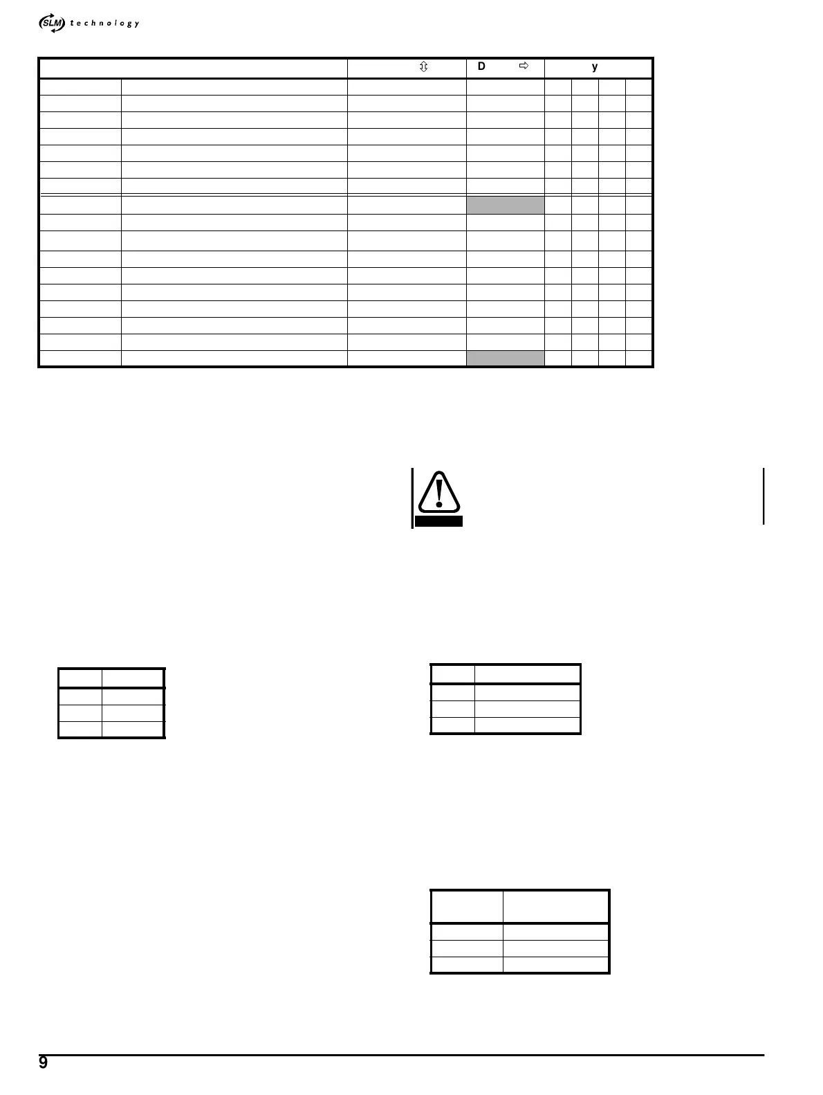
Parameter Range(
ô
)Default(
ð
)Type
3.10 {0.13} Speed-loop proportional gain Kp1 0.0000 ~ 0.3000 0.0100 RW Uni
3.11 {0.14} Speed-loop integral gain Ki1 0.000 ~ 20.000 6.000 RW Uni
3.12 {0.15} Speed-loop derivative gain Kd1 0.0000 ~ 0.1000 0.0000 RW Uni
3.13 Speed-loop proportional gain Kp2 0.0000 ~ 0.3000 0.0100 RW Uni
3.14 Speed-loop integral gain Ki2 0.000 ~ 20.000 6.000 RW Uni
3.15 Speed-loop differential-feedback gain Kd2 0.0000 ~ 0.1000 0.0000 RW Uni
3.16 {0.12} Speed-loop PID gains selector 0 ~ 3 1 RW Uni
3.18 {0.11} Total inertia
0.01 ~ 600.00kgcm
2
RO Uni
3.19 {0.09} Stiffness angle 0 ~ 30.0° 6.0 RW Uni
3.20 {0.10} Load inertia
0.01 ~ 600.00kgcm
2
J
ML
RW Uni
3.57 Speed-loop buffer 1 select 0~1 0 RW Bit
3.58 Speed-loop buffer 2 select 0~1 0 RW Bit
3.59 Speed-loop buffer 3 select 0~1 0 RW Bit
3.60 Speed-loop proportional gain Kp3 0.0000 ~ 0.3000 0.0100 RW Uni
3.61 Speed-loop integral gain Ki3 0.000 ~ 20.000 6.000 RW Uni
3.62 Speed-loop derivative gain Kd3 0.0000 ~ 0.1000 0.0000 RW Uni
3.63 Speed-loop PID buffer in use indicator 0~3
RO Uni
3.16 PID gains
11
22
33
3.16 Select PID buffer...
11
22
33
To select
PID buffer...
Use parameter...
13.57
23.58
33.59
CAUTION