*
M’Ax User Guide 87
Issue Number: 4
Line loading
The Drive loads the EIA485 serial communications lines as follows:
In accordance with the EIA485 specification, the total load on a line must
not exceed 32 unit-loads.
Each transmitter and receiver of the Drive loads the line by two unit-
loads. This allows up to 16 Drives to be linked without the use of line
repeaters.
If a line repeater is added, a maximum of 15 Drives can be linked direct
to the PLC (ie. before the line repeater).
Routing the serial communications cables
A data communications cable should not run parallel to any power
cables, especially any that connect Drives to motors. If parallel runs are
unavoidable, ensure a minimum spacing of 300mm (12 in) between the
communications cable and the power cable.
Where cables are required to cross, they should be at right-angles to
each other in order to minimize coupling.
The maximum cable length for an EIA485 link is 1200 metres (4000
feet).
Devices must be chain-connected on an EIA485 communications link.
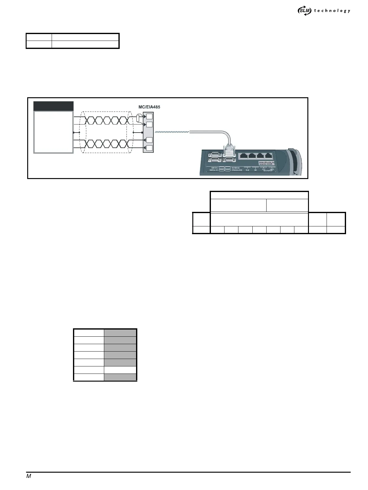
Figure C.1 Connections for an EIA485 4-wire link
Line biasing
Internal 12kΩ bias resistors ensure that logic 1 is detected when the RX
lines are not driven.
Specifying an address
Each device must be programmed by the user to have a two-part
address number in the form
G.U ,whereG is the group number (1 to 9)
and
U is the unit number (1 to 9) in the specified group.
This form of addressing allows the following:
• Anindividualdevicetobeaddressed
• A group of devices to be addressed
• All devices to be addressed
Setting-up procedure
1. Set parameter 0.37 at the required address for the Drive. The value
entered in this parameter must take the form
G.U ,whereG is the
group number (
1 to 9)andU is the unit number (1 to 9)inthe
specified group. The default value is
1.1.Thevalue0 must not be
used.
2. Set parameter
0.36 as follows for the required baud rate:
C.5 Transmitting and receiving data
Fundamentals of data transmission
Data is transmitted at a fixed speed (baud rate) in the form of a
character. A character may typically comprise seven or eight bits.
In order for a receiver to recognise valid data, a start bit, an optional
parity bit and a stop bit are transmitted along with the character, forming
a frame, as shown following.
This is known as a 10-bit frame, since 10 bits in total are transmitted.
The format of the frame is often described as follows:
1 start bit, 7 data bits, even parity, 1 stop bit
lsb = Least-significant bit (ie. bit 0)
msb = Most-significant bit (ie. bit 6)
The parity bit is used by the receiver for checking the integrity of the
data.
Typical-message format
A typical message consists of the following:
• Start control-code
•Deviceaddress
• Parameter number
• Parameter value (data)
• End-of-data control code (ie. stop bit)
• Block checksum (BCC)
Message types
Command
Change the value of a parameter
Enquiry
Enquire the value of a parameter
Reply
Contains a parameter value in response to an enquiry
Acknowledge
Message accepted or rejected, or repeat the last command
Acknowledge messages contain only a control code
RX 2 unit-loads (EIA485)
TX 2 unit-loads (EIA485)
13
14
6
7
RX
RX\
TX
TX\
TX
TX\
RX
RX\
0V
EIA485
interface
PLC
300
600
1200
2400
4800
9600 Default
19200
Low-ASCII character-byte
1st hex
character
2nd hex
character
Start
bit
Sevendatabits
Parity
bit
Stop
bit
0 Isb ... ... ... ... ... msb even 1