*
100 M’Ax User Guide
Issue Number: 4
E.3 Setting-up procedure
1. Referring to the appropriate circuit diagram in Example signal
connections on page 7, identify one digital input and one digital
output that are not used.
2. Make the conections shown in Figure E-1. Use the terminals located
at step 1 for Digital input X and Digital output Y. The interlock circuit
requires a relay having the following specification:
Isolation: 1000V
Coil voltage: 24V
Coil current: 100mA maximum
3. Refer to the following table to identify which Output selection
parameter is related to the digital output being used. Set this
parameter at
10.57.
4. Refer to the following table to identify which Input selection
parameter is related to the digital input being used. Set this
parameter at
10.53.
5. Perform the following, as appropriate:
Version _AN
Initiate the save operation by setting parameter XX.00 at 1000.
Execute the operation by performing either of the following:
• While the display is in Edit mode, press at the same time:
•Setparameter
10.38 at 100 (via serial communications)
Version _SL
Version _AN
(if required)
Ensure the Drive is disabled by checking that the
Hardware enable
contact is open or that parameter 6.15 is set at 0, then perform either
of the following:
• Initiate the store operation by setting parameter
0.50 at 2 (Prog).
Execute the operation by setting parameter
10.38 at 100.
•Set
11.67 Flash update enable at 1.
6. To use the saved values (version _
AN only) after the next power-up,
ensure parameter
0.50 is set at no (0). If you have to change the
setting, immediately afterwards execute the operation, as described
in step 5.
7. To use the stored values after the next power-up, ensure parameter
0.50 is set at 4 (boot2).Ifyouhavetochangethesetting,
immediately afterwards execute the operation, as described in step
5.
8. If the auxiliary back-up supply is to supply power to the motor for
low-speed positioning, for commissioning connect a 1000V
(blocking) diode and a fuse between the positive output of the back-
up supply and terminal
+DC oftheDrive(items12and13inFigure
E-1); this is in addition to the connection to terminal
H.Thefuse
current-rating and the minimum current rating of the diode must be
as follows:
:
9. Make power connections as shown in the Installation Guide (the
power connections shown in Figure E-1 are shown as a guide only).
Example
A M’Ax model 412 remotely controlled by a system controller or PLC
supplying quadrature AB signals (as shown in Figure 2–6).
The
DIGITAL I/O terminals in use are shown in Figure E-2 (below).
Digital output
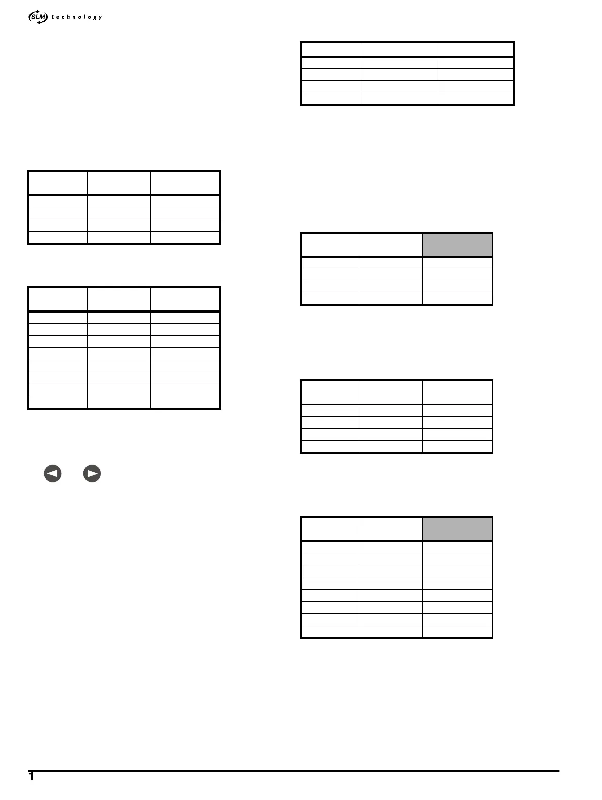
1. RefertoFigureE-2andusethefollowingtabletofindoutwhich
digital outputs are not in use:
2. Select one of the unused digital outputs, for example
Digital output
3
, for the interlock and make connections to it as shown in Figure E-
3.
3. Use the following table to find out which Output selection parameter
to adjust:
4. Set parameter
8.73 at 10.57.
Digital input
5. RefertoFigureE-2andusethefollowingtabletofindoutwhich
digital inputs are not in use:
6. Select one of the unused digital inputs, for example Digital input 5,
for the interlock and make connections to it as shown in Figure E-3.
Digital output
DIGITAL I/O
terminal
Outputselection
parameter
1 5 8.71
2 4 8.72
3 3 8.73
4 2 8.74
Digital output
DIGITAL I/O
terminal
Outputselection
parameter
1108.21
2 9 8.22
3 8 8.23
4 7 8.24
5 1 8.25
6 6 8.26
7138.27
8128.28
and
Model Current rating Fuse rating
M’Ax 403 6A 10A
M’Ax 406 9A 10A
M’Ax 409 12A 16A
M’Ax 412 14A 20A
Digital output
DIGITAL I/O
terminal
15Unused
24Used
33Unused
42Unused
Digital output
DIGITAL I/O
terminal
Outputselection
parameter
158.71
248.72
338.73
428.74
Digital input
DIGITAL I/O
terminal
110Used
29Unused
38Unused
47Unused
51Unused
66Used
713Unused
812Unused