*
6 M’Ax User Guide
Issue Number: 4
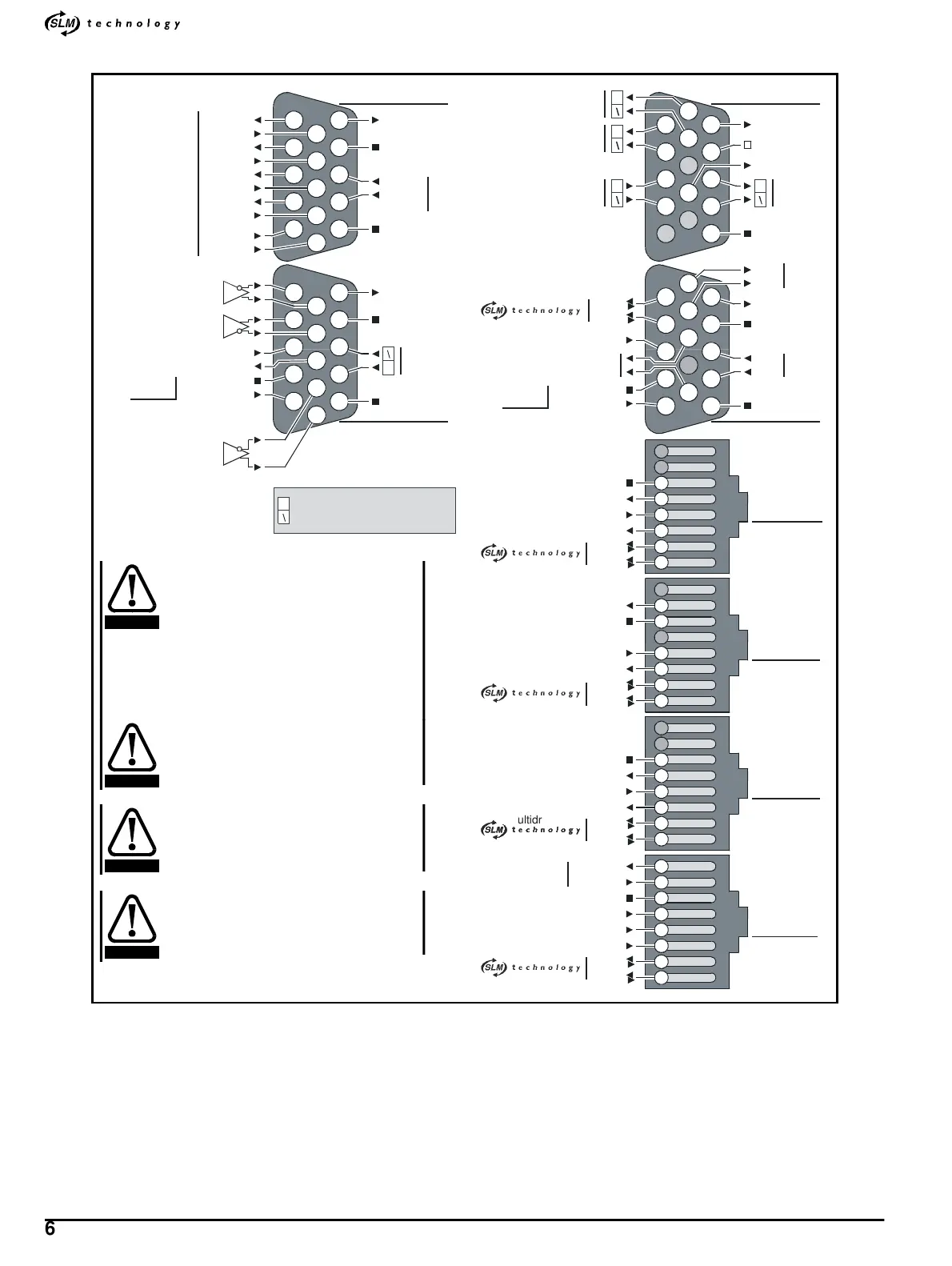
2.4 Functions of the signal terminals
Figure 2-2 Plan view of top of Drive: Functions of the signal
terminals (note that some functions are available only in specific
version(s) of the Drive
For data on each terminal see Appendix A Signal Connectors on page
76.
4
10
9
8
15
14
11
10
8
15
9
15
12
Analog output 2
Analog output 1
0V
Cable shields
Standard-precision
analog input
5
4
3
2
10
9
8
7
15
14
11
24V user supply
0V COMMON
Input 7
Input 8
0V COMMON
Output 1
Input 1
Output 2
Input 2
Output 3
Input 3
Output 4
Input 4
Input 5
Input 6
Z output
9
11
Digital I/O
Digital I/O
Hardware enable
0V COMMON
SLM-and-user
back-up supply
Frequency input
Quad. A input
Direction input
Quad. B input
24V user supply
0V COMMON
High-precision
analog input
7
0V COMMON
6
Touch-trigger
input
12
TX
Status-relay
contact
TX\
24V user supply
0V COMMON
RX
RX\
0V COMMON
EIA 485
7
EIA 485
14
13
13
14
6
7
6
13
12
3
Hardware enable
8
10
DIGITAL I/O SIM ENC
STANDALONE MC/EIA485
11
VCOMMON
24V SLM supply
com\
com\
SLM
ardware enable
rive-status supply
om\
com\
MC
MULTIDROP
OUT
VCOMMON
4V loop
upply
ardware enable
rive-status output
MULTIDROP
IN/PC
VCOMMON
32 TXD
32 RXD
IA232
4V loop input
ardware enable
rive-status input
om\
com\
om\
com\
om\
om\
+24V
2
1
13
12
Non-inverting input/output
Inverting input/output
5
1
6
ardware enable
Drive-status supply
output
A output
+24V
24V user supply
0V COMMON
SLM-and-user
back-up supply
0V COMMON
**
*
*
*
*
ultidrop
ultidrop
Digital output 4
Terminate pulse reference input
connections (frequency / direction or
quadrature inputs) at the Drive by
connecting across the related input
terminals a resistor whose value equals
the characteristic impedance of the cable
that is being used. When more than one
Driveisconnectedaresistorisrequired
only at the last Drive.
0V and 0V common must be used only in
conjunction with their related signal
connections, and must not be used in
place of each other.
Any cable connecting to the SIM ENC
connector should have its cable shield
connected to Pin 15. Failure to do so can
result in damage to the Drive.
Wait 30 seconds after removing power to
the Drive before inserting or removing
control cables as ‘hot plugging’ cables
can result in damage to the Drive or SLM.
CAUTION
CAUTION
CAUTION
CAUTION