*
M’AxUserGuide 5
Issue Number: 4
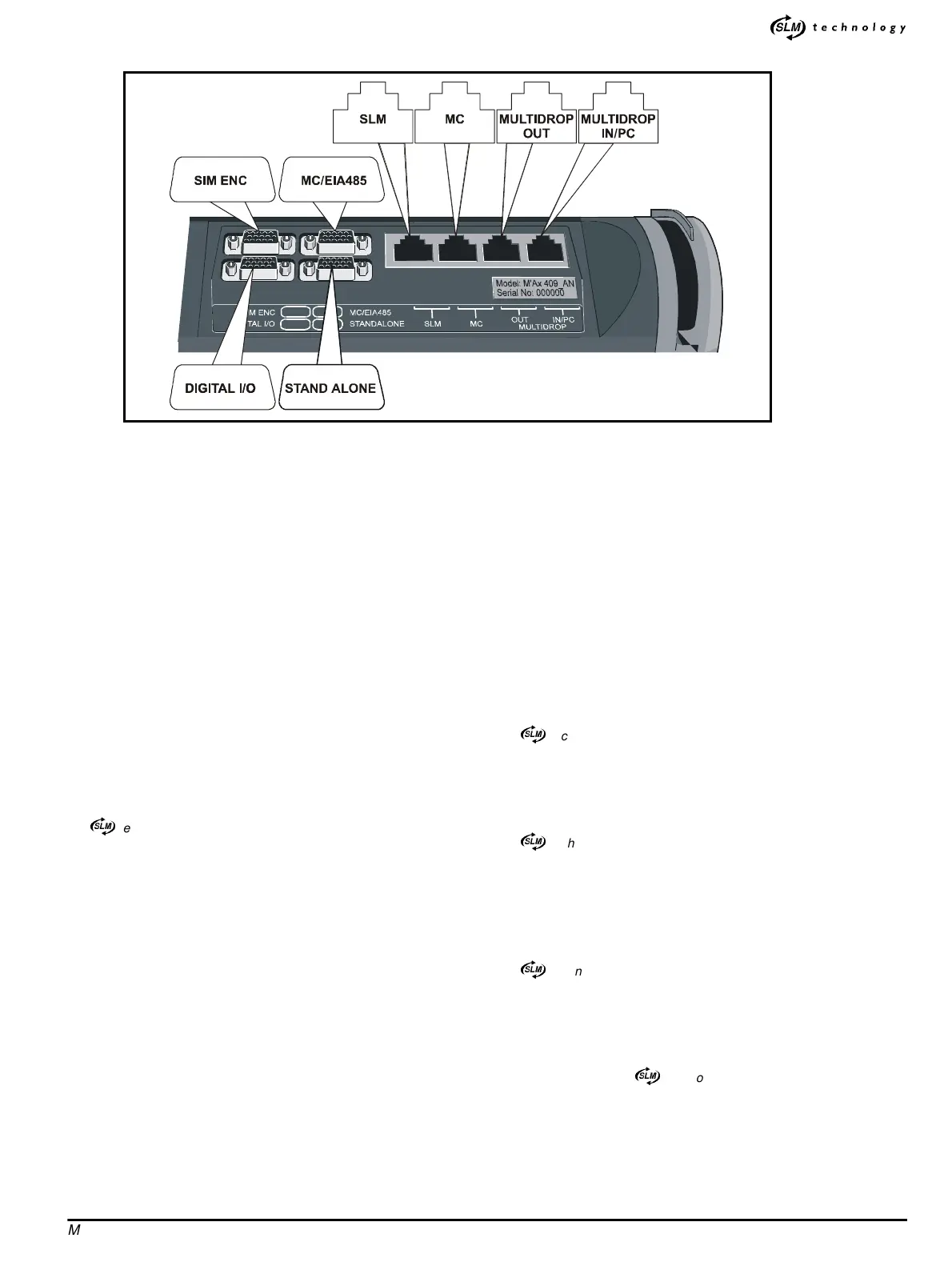
2.2 Locations of the signal connectors
2.3 Functions of the signal connectors
The following functions are available for versions _SL and _AN.
D-type connectors
SIM ENC
(15-way high-density female D-type)
• Simulated-encoder quadrature AB plus Z marker-pulse outputs for
supplying encoder speed and position to a system controller or PLC
or another servo amplifier (following power-up, Z marker-pulses
are produced only after the motor shaft has passed through the
zero position of the feedback encoder; it may then be neces-
sary to adapt the homing procedure accordingly; for more
information, refer to the supplier of the Drive)
• Two analog outputs
• Standard-precision analog speed or torque reference input (version
_SL only)
MC/EIA485
(15-way high-density female D-type)
•
)
technology I/Otoamotioncontroller
• Hardware enable input (electrical enable signal for the Drive)
• Status-relay contact
• Alternative use as an EIA485 port for control from a system control-
ler, PLC or PC
• SLM-and-user back-up supply input for retaining position informa-
tion when the Drive is powered-down (see Back-up supplies later in
this chapter)
• 24V user supply output generated in the Drive (maintained by an
SLM-and-user back-up supply when the Drive is powered-down)
• Status-relay contact
DIGITAL I/O
(15-way high-density male D-type)
• Eight digital inputs for electrical contacts for local or remote (system
controllerorplc)controloftheDrive
• Four digital outputs for local or remote monitoring and/or simple con-
trol of other equipment
• 24V user supply output generated in the Drive (maintained by an
SLM-and-user back-up supply when the Drive is powered-down)
STANDALONE
(15-way high-density male D-type)
• Frequency-and-direction, quadrature square-wave inputs and
directional pulse inputs
• High-precision analog speed or torque reference input (_AN version
only)
• Touch trigger input
• SLM-and-user back-up supply input for retaining position informa-
tion when the Drive is powered-down (see Back-up supplies later in
this chapter)
• 24V user supply output generated in the Drive (maintained by an
SLM-and-user back-up supply when the Drive is powered-down)
RJ45 connectors
SLM
•
)
technology I/O to the SLM
•24V
DC supply to the SLM (maintained by an SLM-and-user back-up
supply when the Drive is powered-down)
• Hardware enable input (electrical enable signal for the Drive)
• Drive-status supply
MC
•
)
technology I/O to a motion controller
• Hardware enable input (electrical enable signal for the Drive)
• Drive-status supply
• 24V user supply output generated in the Drive (maintained by an
SLM-and-user back-up supply when the Drive is powered-down)
MULTIDROP OUT
This connector is active only in version _MD.
•
)
technology I/OtoanotherDriveoperatinginamaster/slave
system
• Hardware enable input (electrical enable signal for the Drive)
• Drive-status output
• +24V loop output
MULTIDROP IN/PC
• Version _MD only:
)
technology I/O to another Drive operating
inamaster/slavesystem
• Hardware enable input (electrical enable signal for the Drive)
• EIA232 communications to a PC running a dedicated application
program (for setting-up purposes only)
• Drive-status input
• +24V loop input
Figure 2-1 Locations of the signal connectors on the top surface of the Drive