*
M’Ax User Guide 99
Issue Number: 4
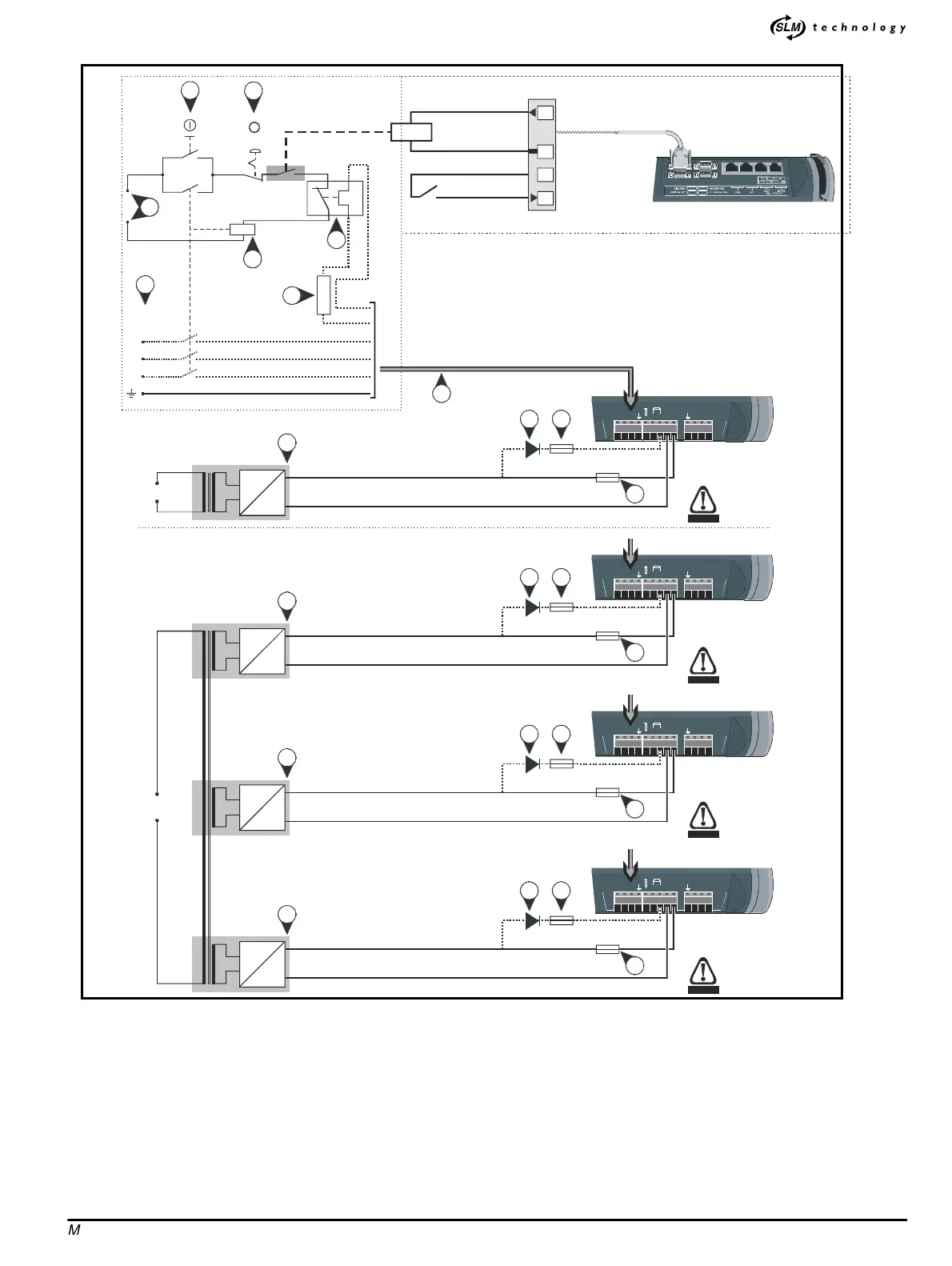
Figure E-1 Auxiliary back-up supply and AC supply connnections
(these are additional to those shown in Figures 2–3 to 2–12)
Key to Figure E-1
1. START/RESET switch (momentary)
2.
STOP switch (latching)
3. Control-circuit supply
4. Contactor coil
5. Thermal-overload protection relay for braking resistor
6. Optional external braking resistor
7.
380 ~ 480VAC supply to the Drive
8. Power connectors on the Drive
9. Interlock relay in contactor circuit
10. Isolated power supply
11. 2A fuse to protect the control circuits
12. 1000V blocking diode is required only when the auxiliary back-up
supply is also to power the motor; the diode to be current-rated
according to the model of Drive being used
13. Fuse required when the auxiliary back-up supply is also to power the
motor;thefusetoberatedaccordingtothemodelofDrivebeing
used
IGITAL I/O
11
15
Digital output Y
0V COMMON
24V user supply
Digital input X
Interlock circuit
UU TRIP
DISABLE
L1
L2
L3
380 ~ 480V
3
φ
1
2
3
4
5
7
6
Contactor
circuit
UVW
LL
23
H
+
AC supply
+
_
~
A
28V - 32V
Auxiliary back-up supply
supplying an individual Drive
1
3
2
10
8
UVW
LL
23
H
+
+
_
~
A
28V - 32V
Auxiliary back-up supplies
supplying a number of Drives
1
3
2
10
UVW
LL
23
H
+
+
_
~
A
28V - 32V
1
3
2
0
UVW
LL
23
H
+
AC supply
+
_
~
A
28V - 32V
1
3
2
0
WARNING
Live circuit
WARNING
Live circuit
WARNING
Live circuit
WARNING
Live circuit