*
60 M’Ax User Guide
Issue Number: 4
Notes
The measurement units for parameters 3.18 and 3.20 depend on the
setting of
5.34 and 5.54.(5.34 = Inertia units and 5.54 = Inertia range.)
Parameter
3.64: sampletime=250µs
Parameter
3.23 canbeusedforsettingafineanalogoffsetortrim;
resolution = 0.1RPM
See Appendix D Optimising the Dynamic Performance on page 93.
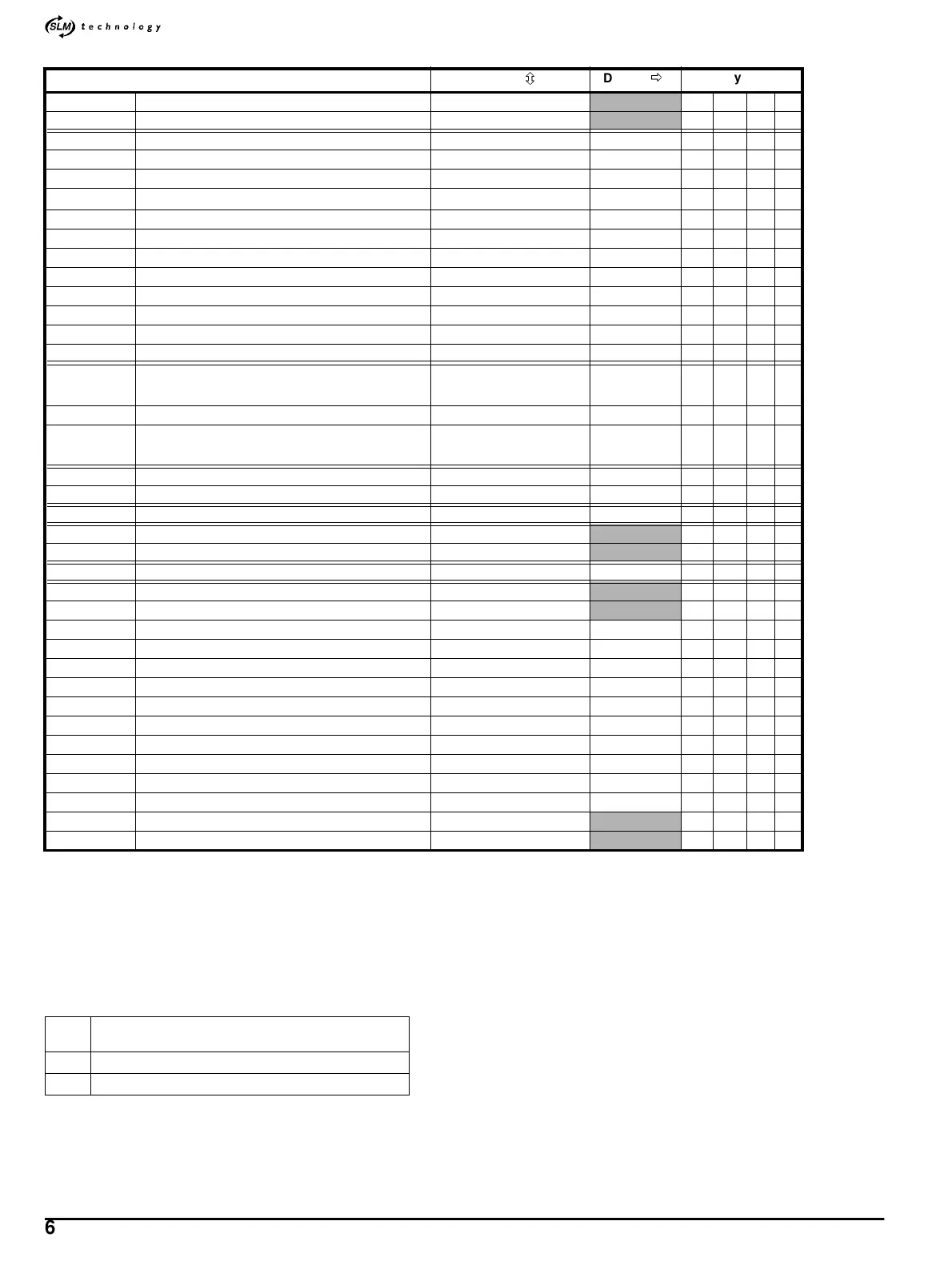
Parameter
Range(
ô
)Default(
ð
)
Type
3.01 {0.04} Final speed reference ±[1.06] RPM RO Bi P
3.02 {0.05} Speed feedback ±[1.06] RPM
RO Bi P
3.05 Zero-speed threshold 0 ~ 200 RPM 5 RW Uni
3.06 At-speed lower limit 0 ~ [1.06] RPM 5 RW Uni
3.07 At-speed upper limit 0 ~ [1.06] RPM 5 RW Uni
3.08 Over-speed threshold
0~n
MAX
RPM
0RWUni
3.09 Absolute at-speed detect mode select 0 ~ 1 0 RW Bit
3.10 {0.13} Speed-loop proportional gain Kp1 0.0000 ~ 0.3000 [SLM] RW Uni
3.11 {0.14} Speed-loop integral gain Ki1 0.000 ~ 20.000 [SLM] RW Uni
3.12 {0.15} Speed-loop derivative gain Kd1 0.0000 ~ 0.1000 [SLM] RW Uni
3.13 Speed-loop proportional gain Kp2 0.0000 ~ 0.3000 [SLM] RW Uni
3.14 Speed-loop integral gain Ki2 0.000 ~ 20.000 [SLM] RW Uni
3.15 Speed-loop differential-feedback gain Kd2 0.0000 ~ 0.1000 [SLM] RW Uni
3.16 {0.12} Speed-loop PID gains selector 0 ~ 3 1 RW Uni
3.18 Total inertia
0.1 ~ 6000.0 kgcm
2
or
0.00001 ~ 0.6 kgm
2
J
t
RO Uni
3.19 {0.09} Stiffness angle 0.0 ~ 30.0
° 6.0 RW Uni
3.20 {0.10} Load inertia
0.1 ~ 6000.0 kgcm
2
or
0.00001 ~ 0.6 kgm
2
J
L
RW Uni
3.22 Hard speed reference ±500.0 RPM 0.0 RW Bi
3.23 Hard speed reference selector 0~1 0 RW Bit
3.25 Feedback-encoder phase offset 0 ~ 65535 REV/65536 [SLM] RO Uni
3.28 {0.28} Feedback-encoder revolution counter 0 ~ 65535 REV
RO Uni
3.29 {0.29} Feedback-encoder position 0 ~ 65535 REV/65536
RO Uni
3.32 Z marker pulse received indicator 0~1 RO Bit
3.51 High resolution Marker select 0
RW Bit
3.52 Z marker pulse offset 0 ~ 65535 REV/65536
RO Uni
3.53 Shaft-key offset 0 ~ 65535 REV/65536 [SLM] RO Uni
3.54 Zero offset ±180
° 0RWUni
3.55 Number of encoder lines 1024, 2048, 4096, 8192 4096 RW Uni
3.56 F/D mode select 0~1 0 RW Bit
3.57 Speed-loop PID buffer 1 select 0~1 0 RW Bit
3.58 Speed-loop PID buffer 2 select 0~1 0 RW Bit
3.59 Speed-loop PID buffer 3 select 0~1 0 RW Bit
3.60 Speed-loop proportional gain Kp3 0.0000 ~ 0.3000 [SLM] RW Uni
3.61 Speed-loop integral gain Ki3 0.000 ~ 20.000 [SLM] RW Uni
3.62 Speed-loop derivative gain Kd3 0.0000 ~ 0.1000 [SLM] RW Uni
3.63 Speed-loop PID buffer in use indicator 0~3
RO Uni
3.64 Speed feedback (unfiltered) ±2048
RO Bi
J
M
Motor inertia
(defined by the motor via the
SLM,Pr5.33)
J
L
Load inertia
J
t
Total inertia = J
M
+J
L