*
62 M’Ax User Guide
Issue Number: 4
Notes
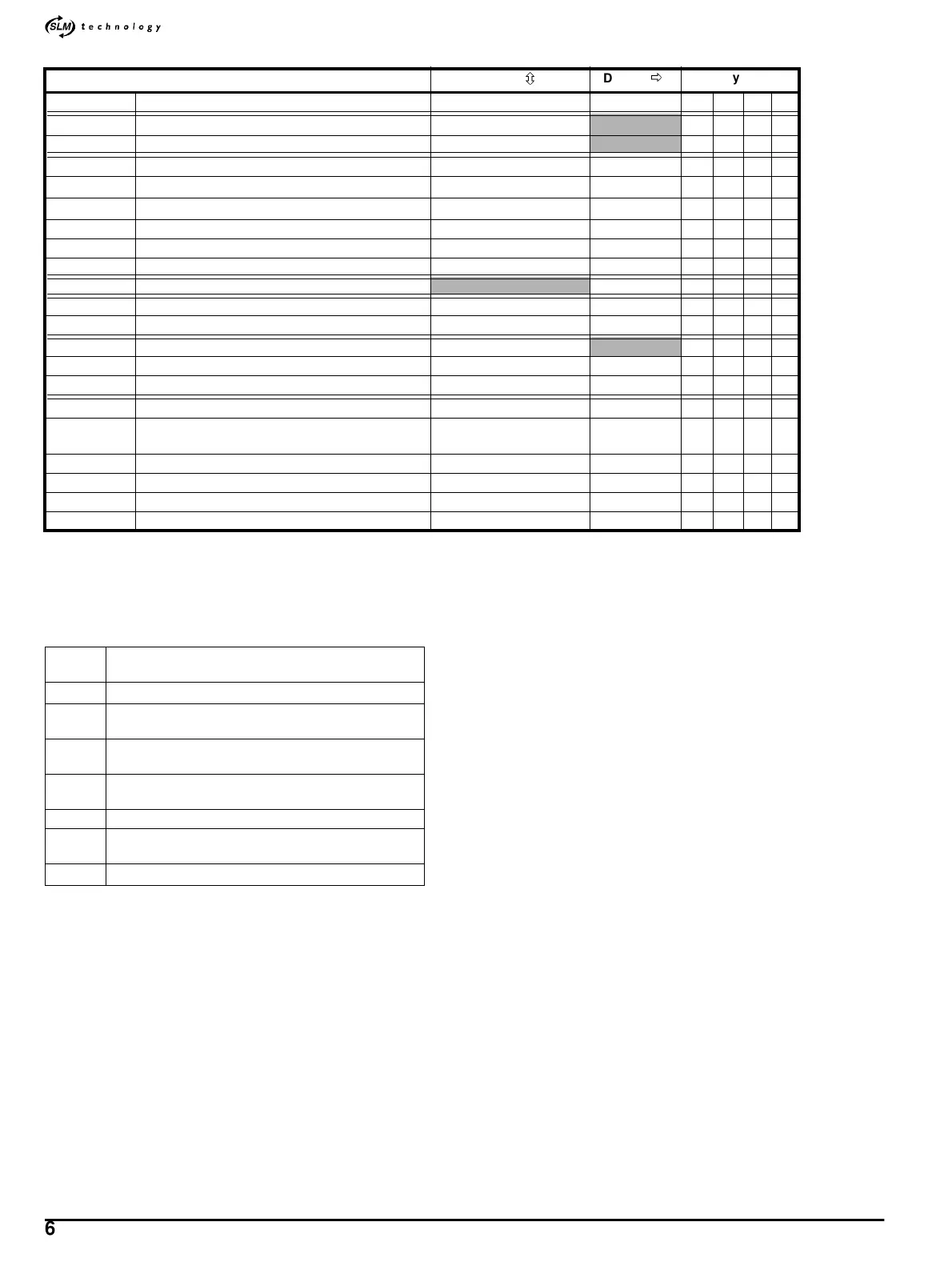
Parameters 4.52, 4.53, 4.54: see section F.2 Adjusting the threshold for
the motor thermal-overload alarm on page 105.
Parameter
4.04: the range 0~620represents 0 ~ 200% FLC
Parameter
Range(
ô
)Default(
ð
)
Type
4.01 {0.07} Motor current magnitude
0~I
OL
A
RO Uni P
4.03 Torque demand
±200.0 %I
T
A
RO Bi P
4.04 Current demand 0 ~ 620
RO Uni P
4.07 {0.18} Symmetrical current limit Kc1
0 ~ 300.0 % I
M
200.0 RW Uni
4.08 Torque reference
±200.0 %I
LIM
0.0 RW Bi
4.09 Torque-reference offset
±200.0 %I
LIM
0.0 RW Bi
4.10 Torque-reference offset enable 0~1 0 RW Bit
4.11 Torque mode selector 0 ~ 1 0 RW Uni
4.12 {0.16} Current-demand filter 1 cut-off frequency 0 ~ 1200 Hz 500 RW Uni
4.15 Motor - thermal time-constant
[SLM] RO Uni
4.23 Current-demand filter 2 cut-off frequency 0 ~ 1200 Hz 500 RW Uni
4.24 Symmetrical current limit Kc2
0 ~ 300.0 % I
M
200.0 RW Uni
4.26 Torque-compensation gain 0 ~ 5000 rads/s
RW Uni
4.27 Current-demand filter 3 cut-off frequency 0 ~ 1200 Hz 500 RW Uni
4.28 Symmetrical current limit Kc3
0 ~ 300.0 % I
M
200.0 RW Uni
4.52 Motor thermal-overload alarm level
0~125%I
M
110 RW Uni
4.53
Symmetrical current limit after motor thermal-
overload alarm
0~300%I
M
105 RW Uni
4.54 Thermal-overload time to trip 0 ~ 200 s 10 RW Uni
4.55 SLM overheat threshold 0 ~ 100
°C85RWUni
4.56 ‘U’ phase current loop offset correction 0 ~ 65535 0 RW Uni
4.57 ‘V’ phase current loop offset correction 0 ~ 65535 0 RW Uni
FLC
Full-load current (continuous-current rating of the
Drive)
I
OL
Maximum overload current from the Drive [2 x FLC]
I
M
Rated continuous motor-current (defined by the motor
via the SLM)
I
T
Maximum torque-producing current (derived from
[FLC x kT])
I
LIM
Value of the current limit that is obtained from the
setting of
4.07 Symmetrical current limit
LT Trip level of the Drive thermal-overload accumulator
n
MAX
Maximum speed of the motor (defined by the motor via
the SLM)
J
M
Motor inertia (defined by the motor via the SLM)