*
82 M’Ax User Guide
Issue Number: 4
SLM
MC
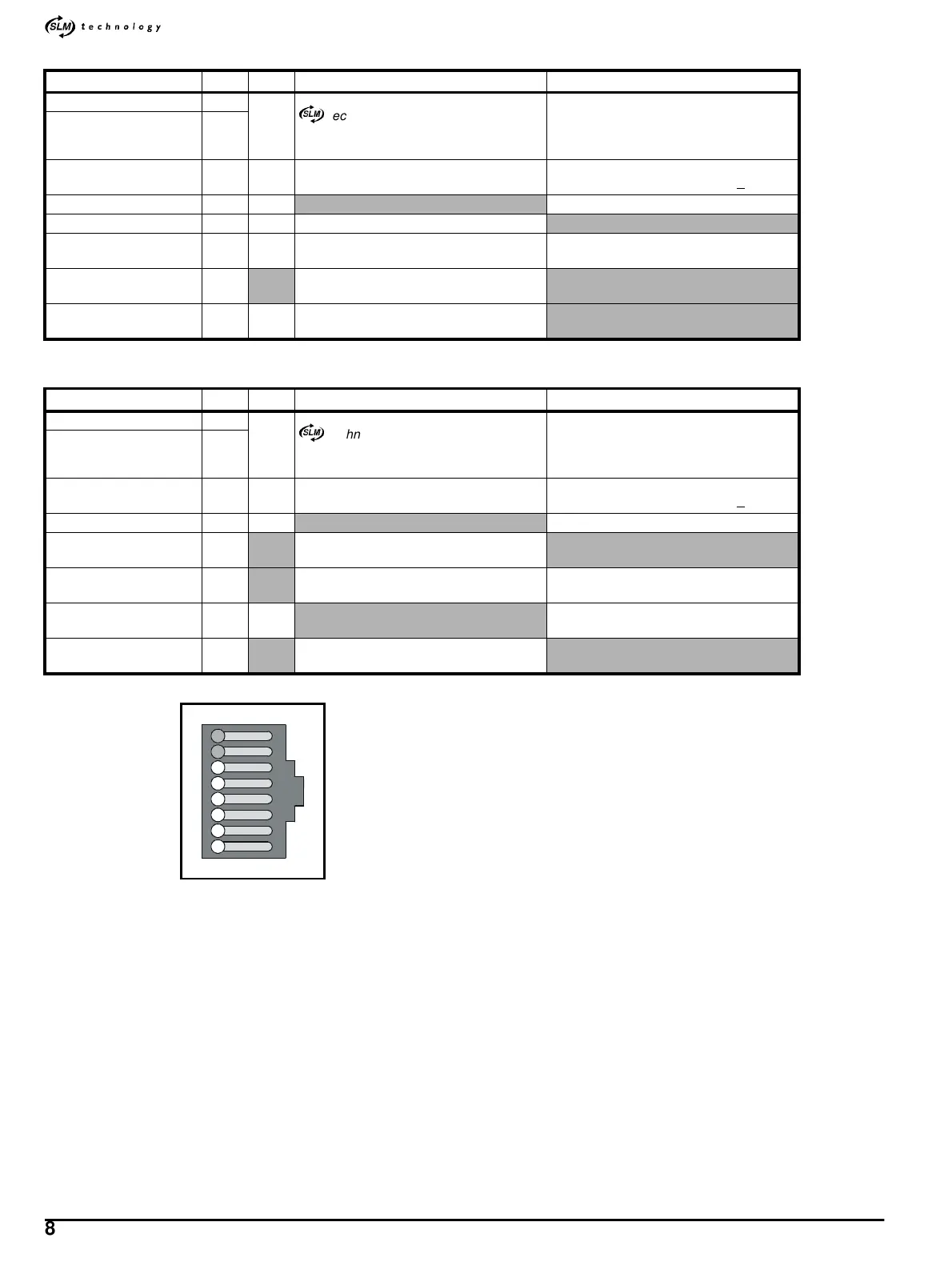
Figure A.5 RJ45 connector pin-locations (as seen from the top of
the Drive)
Name Pin I/O Function Specification
com 1
I/O
)
technology port for communication
with the SLM
2-wire EIA485
100
Ω twisted-pair inside 8-way shielded
cable (see Cables and connectors on page
76)
com\ 2
Drive-status supply 3 O
For use with Drive-status input and output
connections
Current-source supply
Output-voltage compliance: 24V +20%
Hardware enable 4 I
(See Digital inputs on page 77.)
24V SLM supply 5 O 24V supply to the SLM
0V COMMON 6 For use with all the I/O on this connector
0V COMMON must not be interchanged
with 0V
(No connections)
7
8
Do not use
Cable shield Shell
Connect the cable shield to the connector
shell
Name Pin I/O Function Specification
com 1
I/O
)
technology port for communication
withamotioncontroller
2-wire EIA485
100
Ω twisted-pair inside 8-way shielded
cable (see Cables and connectors on page
76)
com\ 2
Drive-status supply 3 O
For use with Drive-status input and output
connections
Current-source supply
Output-voltage compliance: 24V +20%
Hardware enable 4 I
(See Digital inputs on page 77.)
(No connections)
5
8
Do not use
0V COMMON 6 For use with all the I/O on this connector
0V COMMON must not be interchanged
with 0V
SLM-and-user back-up
supply
7I
(See Types of back-up supplies on page
17.)
Cable shield Shell
Connect the cable shield to the connector
shell
6
7
8
5
4
3
2
1