Midi-Maestro and Maxi Maestro Drive
17
Adjusting the peak current
RIP resistor
When a
RIN resistor is fitted, I
PEAK
may become
excessively high in relation to I
NOM
. To reduce the
value of the peak current, use a
RIP resistor.
Note
The new value for I
PEAK
must be ignored when the
value of
RIN is calculated.
Use the following equation to calculate the value of the
RIP resistor:
(())
(())
RIP =
2200 I
I-I
k
LIM
PEAK LIM
××
ΩΩ
Where:
I
LIM = the new value required for I
PEAK
Note
When the peak current is reduced, the ratio between
I
PEAK
and I
NOM
is altered. This alteration increases the
time before I
2
t protection takes place.
In this case, the peak current is supplied for more
than 2 seconds.
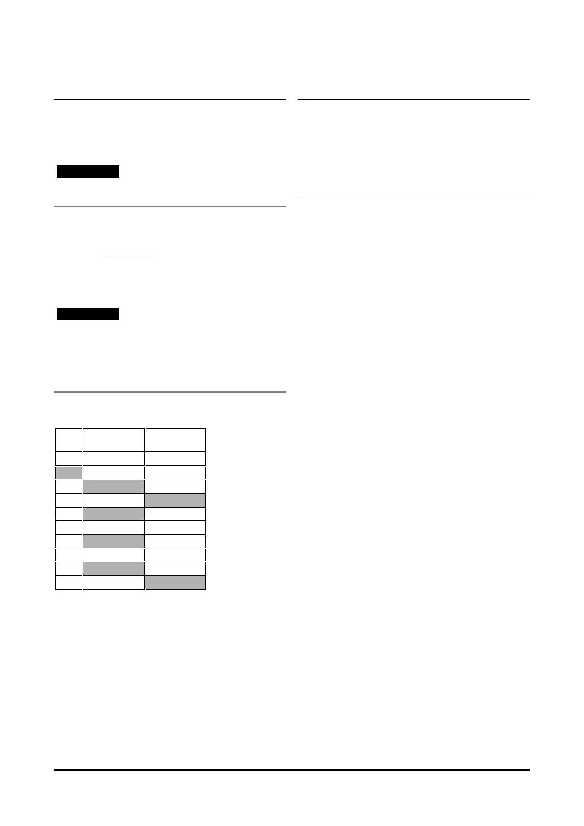
The following table may be used for finding an
approximate value for I
PEAK
.
RIP Midi-Maestro
140 ×× 8/16
Midi-Maestro
140 ×× 14/28
kΩΩ
I
PEAK
I
PEAK
16 28
15.0 26
12.0 14
8.6 24
6.8 12 22
5.6 20
3.9 10 18
2.7 16
2.2 8
Zero speed torque
RS resistor
No resistor is fitted as standard. Mount an
RS resistor
to adjust the amount of torque current to be applied to
the motor when the Drive has received a
STOP
command.
Dynamic calibration
For modifying the settings, the following equipment is
required:
Low frequency function generator
Frequency range: 0Hz to 10MHz
Output voltage: –3.5V to +3.5V
Twin-trace storage oscilloscope.
1. Remove the speed reference signal from pins 9
and 10.
2. Connect the function generator output to pins 9
and 10.
3. Set the function generator at the following:
Square wave output
Amplitude: ±2V
Frequency: 0.2Hz
4. Connect oscilloscope channel A to pin 11.
5. Connect oscilloscope channel B to pin 1.
6. Connect oscilloscope ground to pin 8.
7. Connect the oscilloscope external trigger input to
the function generator output.
8. Set the oscilloscope as follows:
Sensitivity: 1mV per division
Timebase: 20ms per division