10 Unidrive SP Low Voltage DC Installation Guide
www.controltechniques.com Issue Number: 1
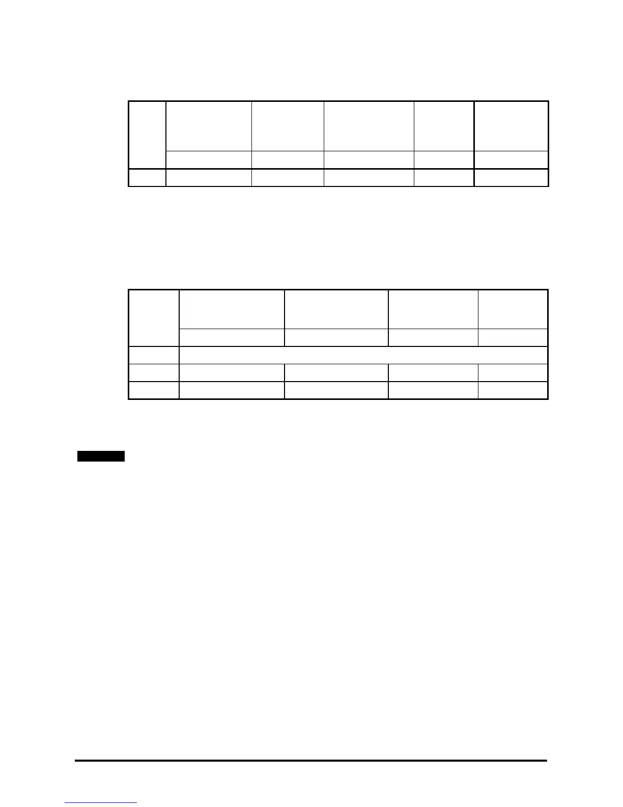
3.1.3 Drive control 24V rating
The table below shows the specification of the control +24V external input terminal that
the user supply should meet.
Table 3-2 Drive control 24V rating
Minimum and maximum voltage values include ripple and noise. Ripple and noise levels
must not exceed 5%.
3.1.4 24V Low Voltage DC mode enable rating
Table 3-3 shows the specification of the 24V Low Voltage DC mode enable terminal that
the user supply should meet.
Table 3-3 Low voltage DC mode enable rating
Minimum and maximum voltage values include ripple and noise. Ripple and noise levels
must not exceed 5%.
Drive
size
Maximum
continuous
operating voltage
Minimum
continuous
operating
voltage
Nominal
continuous
Operating voltage
Minimum
start up
voltage
Nominal
current
consumption
VV VVmA
All 30 19.2 24 21.6 500
Drive size
Maximum continuous
operating voltage
Minimum continuous
operating voltage
Nominal
continuous
operating voltage
Nominal
current
consumption
VVVmA
1 to 3 N/A
4 to 6 30 19.2 24 500
SPMA/D 30 19.2 24 500
A common supply can be used for the drive control 24V and 24V Low Voltage DC mode
enable.
NOTE