Unidrive SP Low Voltage DC Installation Guide 37
Issue Number: 1 www.controltechniques.com
Safety Information Introduction Product information System design
Component data
Index
3. Check that the chosen resistor can tolerate the overload
Use the maximum time tripping curve to determine the time that corresponds to a factor
(F) of 7.3
From the maximum time tripping curve you get a time of approximately 10 seconds for a
factor (F) of 7.3.
Check that the braking resistor can tolerate 9.2A for 10 seconds.
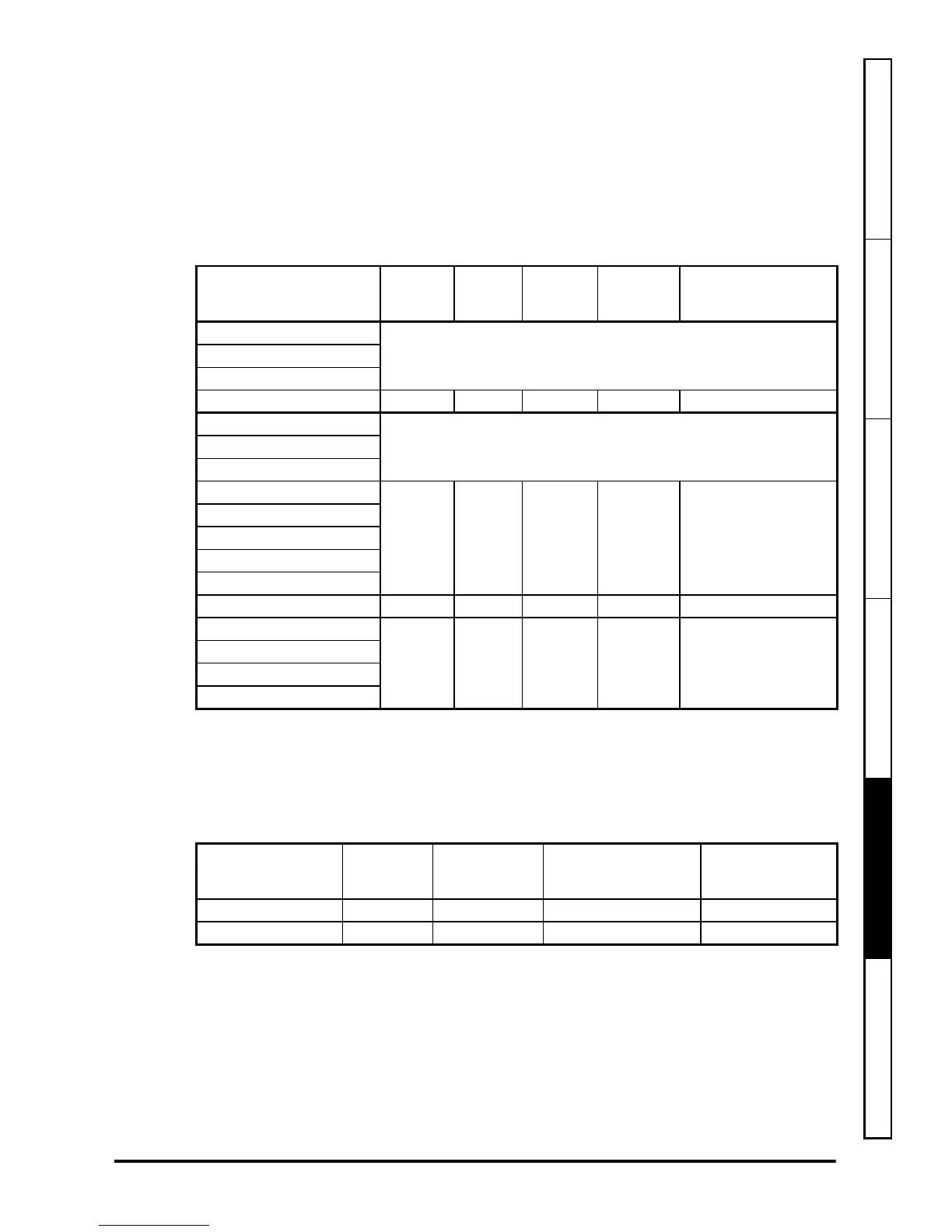
5.4 External soft start resistor
Table 5-6 Resistor values
5.4.1 External soft start resistor protection
To protect the soft start resistor from becoming damaged in a failure situation a suitable
fuse needs to be fitted in series with the resistor. The fuse must meet the specification
as detailed below.
Table 5-7 Fuse values
Alternative fuse types.
An alternative to the fuses recommended in Table 5-7 can be used providing the fuse
time vs current characteristic lies between the curves shown in the graphs below and
the voltage rating is as per the value shown in Table 5-7.
Drive
Rs
(Ω)
Power
rating
(W)
Energy
rating
(J)
Resistor
part
number
Resistor
combination
SP1202 to SP1204
N/ASP2201 to SP2203
SP3201 to SP3202
SP4201 to SP4203 48 148 1700 1270-2483 1270-2483
SP1401 to SP1406
N/ASP2401 to SP2404
SP3401 to SP3403
SP4401 to SP4403
96 296 3400 1270-2483 2x1270-2483 in series
SP5401 to SP5402
SP6401 to SP6402
SPMA1401 to SPMA1402
SPMD1401 to SPMD1404
SP3501 to SP3507 N/A N/A N/A N/A N/A
SP5601 to SP5602
96 296 3400 1270-2483 2x1270-2483 in series
SP6601 to SP6602
SPMA1601 to SPMA1602
SPMD1601 to SPMD1604
Drive voltage rating
(V)
F4 current
rating
(A)
F4 DC voltage
rating
(V)
Recommended Fuse
type
(Ferraz)
Alternative fuse
type
200 1 500 ATM As set out below
400/575/690 1 1000 A 120X As set out below