32 Unidrive SP Low Voltage DC Installation Guide
www.controltechniques.com Issue Number: 1
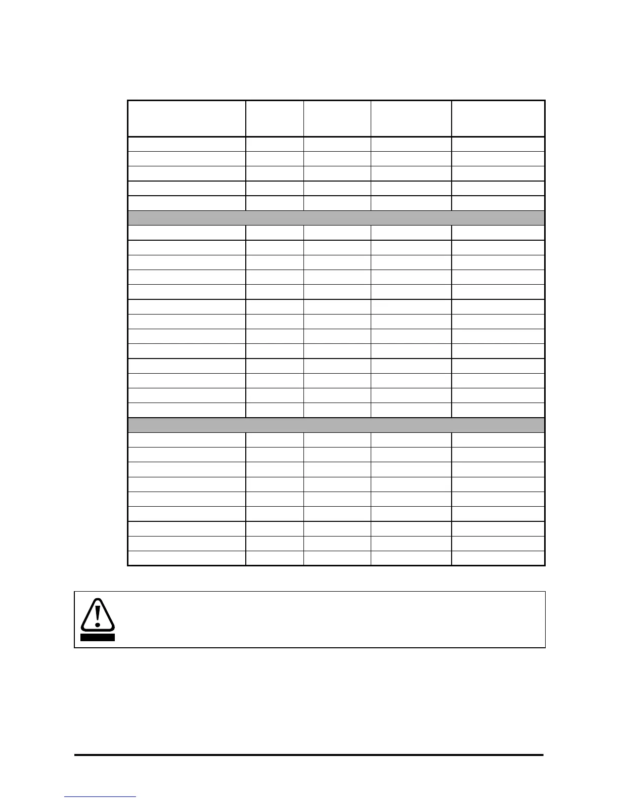
5.2 Discharge resistor and protection
The discharge resistor is required to discharge the DC bus of the drive whilst changing
from one supply to the other.
Table 5-3 Discharge resistor and protection values
*The chosen thermal overload relay must have a class 10 trip characteristic.
Drive
Rdis
(Ω)
Total Power
rating
(W)
Short term (1s)
energy rating
(J)
Thermal overload
relay trip setting
(A)*
SP1201 to SP1202 220 6 3950 0.13
SP1203 to SP1204 100 4 2580 0.25
SP2201 to SP2203 100 6 4030 0.34
SP3201 to SP3202 100 12 8670 0.48
SP4201 to SP4203 100 9 6470 0.48
SP1401 to SP1406 680 17 12180 0.1
SP2401 to SP2404 220 6 3940 0.25
SP3401 to SP3403 220 11 7720 0.32
SP4401 220 9 6660 0.3
SP4402 to SP4403 100 18 13050 0.6
SP5401 to SP5402 100 25 18330 0.79
SP6401 100 33 24510 1.0
SP6402 100 49 36250 1.1
SPMA1401 100 33 24510 1.0
SPMA1402 100 49 36250 1.1
SPMD1401 100 33 24510 1.0
SPMD1402 100 49 36250 1.1
SPMD1403 to SPMD1404 100 62 46560 1.1
SP3501 to SP3507 220 12 8870 0.35
SP5601 to SP5602 100 23 17210 0.8
SP6601 to SP6602 100 35 25850 0.9
SPMA1601 100 35 25850 0.9
SPMA1602 100 35 25850 0.9
SPMD1601 100 35 25850 0.9
SPMD1602 100 35 25850 0.9
SPMD1603 100 37 27230 1.0
SPMD1604 100 37 27230 1.1
High temperatures
The discharge resistor can reach high temperatures. Locate the resistors so that
damage cannot result. Use cable having insulation capable of withstanding high
temperatures.
WARNING